 ALLPCB


When it comes to assembling printed circuit boards (PCBs) with both surface mount and through-hole components, choosing the right soldering method is critical for efficiency, reliability, and cost-effectiveness. Two popular techniques for mixed technology assembly are the pin-in-paste assembly process and wave soldering for through-hole components. But which method is best for your project? In short, pin-in-paste offers a streamlined, reflow-based approach ideal for automated processes and smaller components, while wave soldering excels in high-volume production with larger through-hole parts. In this blog, we’ll dive deep into a mixed technology soldering methods comparison, exploring the pros, cons, and best use cases for each technique to help you make an informed decision.
What is Mixed Technology Assembly?
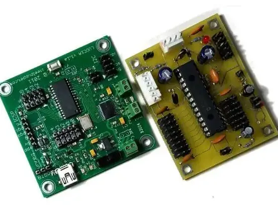
Mixed technology assembly refers to the process of building PCBs that include both surface mount devices (SMDs) and through-hole components (THCs). SMDs are smaller and soldered directly onto the surface of the board, while THCs have leads that pass through holes in the PCB and are soldered on the opposite side. This combination is common in modern electronics, as it allows for compact designs while maintaining the durability and power-handling capabilities of through-hole parts. However, soldering these different types of components requires specialized techniques, which is where pin-in-paste and wave soldering come into play.
Understanding the Pin-in-Paste Assembly Process
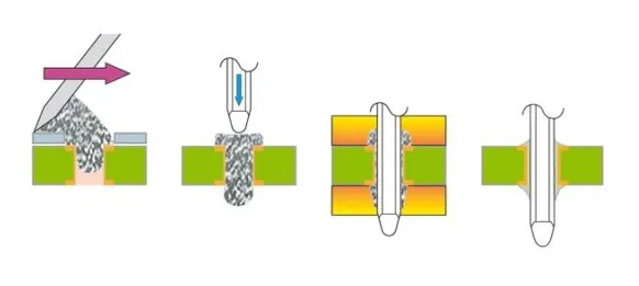
The pin-in-paste assembly process, also known as through-hole reflow, is a method that allows through-hole components to be soldered using the same reflow soldering process used for SMDs. Instead of a separate soldering step, solder paste is applied to the through-hole pads or directly into the holes. The component leads are then inserted into the paste-filled holes, and the entire board is passed through a reflow oven. The heat melts the solder paste, forming a strong joint around the leads.
Advantages of Pin-in-Paste
- Streamlined Production: Since pin-in-paste uses the same reflow process as SMDs, it eliminates the need for a separate soldering step, reducing production time by up to 30% in some cases.
- Automation-Friendly: This method integrates seamlessly with automated SMT (surface mount technology) assembly lines, minimizing manual labor.
- Cost-Effective for Low Volumes: For smaller production runs, pin-in-paste avoids the setup costs associated with wave soldering equipment.
- Reduced Thermal Stress: Unlike wave soldering, which exposes the entire board to a molten solder wave, pin-in-paste uses controlled reflow profiles, reducing thermal shock to sensitive components.
Challenges of Pin-in-Paste
- Limited to Smaller Components: Pin-in-paste works best for smaller through-hole components with shorter leads. Larger parts may not receive enough solder for a reliable joint, leading to potential failures.
- Solder Voiding: Improper paste application or reflow profiles can result in voids or insufficient solder fill, compromising joint strength. Studies show voiding rates can reach 10-15% if not optimized.
- Design Constraints: PCB design must account for hole size and lead diameter to ensure proper solder flow. A mismatch can lead to poor connections.
Exploring Wave Soldering for Through-Hole Components
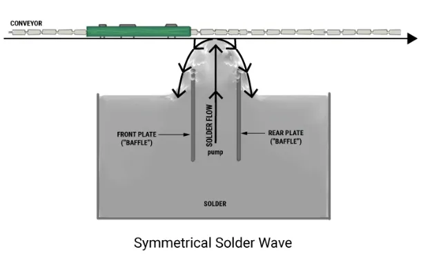
Wave soldering for through-hole components is a traditional method widely used in high-volume PCB assembly. In this process, the PCB is passed over a wave of molten solder, which flows into the through-hole leads and forms a bond as it cools. Wave soldering is typically performed after SMDs are reflow-soldered in a separate step, making it a two-stage process for mixed technology boards.
Advantages of Wave Soldering
- High Throughput: Wave soldering is ideal for large-scale production, capable of processing hundreds of boards per hour, making it a go-to for mass manufacturing.
- Reliable for Large Components: This method ensures complete solder fill for larger through-hole components like connectors and capacitors, reducing the risk of weak joints.
- Proven Technology: Wave soldering has been used for decades and is well-understood, with established best practices for consistent results.
Challenges of Wave Soldering
- Two-Step Process: Since wave soldering cannot be used for SMDs, mixed technology boards require a separate reflow step, increasing production time and cost by approximately 20-40% compared to a single-step process.
- Thermal Stress: The molten solder wave can cause thermal shock to components, potentially leading to damage or reduced lifespan, especially for heat-sensitive parts.
- Masking Requirements: Areas of the PCB that should not be soldered (like SMDs) must be masked or protected, adding complexity and cost to the process.
Mixed Technology Soldering Methods Comparison: Key Factors to Consider
In this mixed technology soldering methods comparison, we’ll break down the critical factors that influence the choice between pin-in-paste and wave soldering. Understanding these aspects will help you align the soldering method with your project’s specific needs.
1. Production Volume
For low to medium production volumes (under 1,000 units), pin-in-paste is often more cost-effective due to its single-step process and compatibility with automated SMT lines. In contrast, wave soldering shines in high-volume production (over 5,000 units), where the initial setup costs are offset by faster throughput rates of up to 200 boards per hour.
2. Component Size and Type
Pin-in-paste is best suited for smaller through-hole components with lead diameters under 1.2 mm and hole sizes between 1.5 to 2.0 times the lead diameter to ensure proper solder flow. Wave soldering, however, is more reliable for larger components with lead diameters exceeding 1.5 mm, as the wave ensures complete solder coverage even in deeper holes.
3. Thermal Sensitivity
If your board includes heat-sensitive components, pin-in-paste is the safer choice. Reflow ovens allow precise control over temperature profiles, typically peaking at 245°C for lead-free solder, minimizing thermal stress. Wave soldering, with solder bath temperatures often exceeding 260°C, poses a higher risk of damage to delicate parts.
4. Cost and Equipment
Pin-in-paste leverages existing SMT reflow equipment, reducing the need for additional machinery and lowering upfront costs by as much as 15-25% compared to wave soldering setups. However, wave soldering machines, while expensive (often costing $50,000 or more), provide long-term savings in high-volume scenarios due to their speed and efficiency.
5. Design Flexibility
Wave soldering offers greater flexibility for complex designs with a high density of through-hole components, as it can handle a wide range of part sizes and board layouts. Pin-in-paste requires more precise design considerations, such as optimizing hole-to-lead ratios and ensuring uniform solder paste application, which can limit design freedom.
Best Practices for Pin-in-Paste Assembly
To achieve optimal results with the pin-in-paste assembly process, follow these practical tips:
- Optimize Solder Paste Volume: Use a stencil design that deposits 30-50% more solder paste than for SMD pads to ensure sufficient fill in through-holes. Overprinting techniques can help achieve this.
- Control Reflow Profile: Adjust the reflow oven temperature to peak at 235-245°C for lead-free solder, with a soak time of 60-90 seconds to allow proper wetting and minimize voiding.
- Select Compatible Components: Choose through-hole components with shorter leads (under 3 mm protrusion) to prevent solder bridging or insufficient fill.
Best Practices for Wave Soldering
For successful wave soldering for through-hole components, consider these guidelines:
- Preheat the Board: Preheat the PCB to 100-120°C before it contacts the solder wave to reduce thermal shock and improve solder flow.
- Use Proper Flux: Apply a no-clean or water-soluble flux to enhance wetting and prevent oxidation during the wave soldering process.
- Protect SMDs: Use heat-resistant tape or conformal coating to shield surface mount components from the solder wave, ensuring they are not damaged or dislodged.
Real-World Applications: When to Choose Each Method
Understanding where each method excels can guide your decision. For example, pin-in-paste is often used in consumer electronics like smartphones and wearables, where boards are compact, production runs are moderate, and automation is key. A typical smartphone PCB might have 80% SMDs and 20% small through-hole connectors, making pin-in-paste ideal for a single reflow pass.
On the other hand, wave soldering is preferred in industrial applications, such as power supplies or automotive control units, where larger through-hole components like high-power resistors and heavy connectors dominate. These projects often involve production runs exceeding 10,000 units, justifying the setup cost of wave soldering equipment.
Conclusion: Making the Right Choice for Your Project
Choosing between the pin-in-paste assembly process and wave soldering for through-hole components depends on your specific project requirements. Pin-in-paste offers a modern, efficient solution for smaller components and lower to medium production volumes, integrating seamlessly with SMT processes. Wave soldering remains the gold standard for high-volume production and larger through-hole parts, delivering reliability and speed at scale. By considering factors like production volume, component types, thermal constraints, and cost, you can select the method that best aligns with your needs.
At ALLPCB, we’re committed to helping you navigate the complexities of mixed technology assembly. Whether you opt for pin-in-paste or wave soldering, our expertise and advanced manufacturing capabilities ensure your PCBs meet the highest standards of quality and performance. Dive into your next project with confidence, knowing you’ve chosen the right soldering method for success.


