 ALLPCB


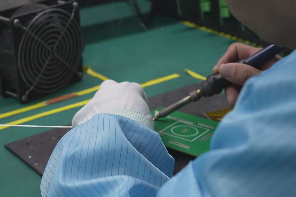
Hand soldering remains a cornerstone of printed circuit board (PCB) assembly, particularly for odd-form components - those uniquely shaped or oversized parts that don't fit neatly into automated assembly processes. These components, such as large connectors, transformers, or custom mechanical parts, often require manual soldering due to their size, shape, or placement complexity. However, achieving high-quality solder joints for these components demands precision, skill, and robust quality control (QC) measures. Poor soldering can lead to defects like cold joints, solder bridges, or insufficient wetting, which compromise the reliability of the PCB. In this blog, we explore the challenges of hand soldering odd-form components, best practices for quality control, and actionable techniques to ensure reliable, high-performance assemblies.
Our goal is to provide engineers with practical insights to improve soldering outcomes while addressing common pain points. Whether you're assembling prototypes or high-reliability boards for aerospace or medical applications, mastering quality control in hand soldering is critical to success.
Understanding Odd-Form Components in PCB Assembly
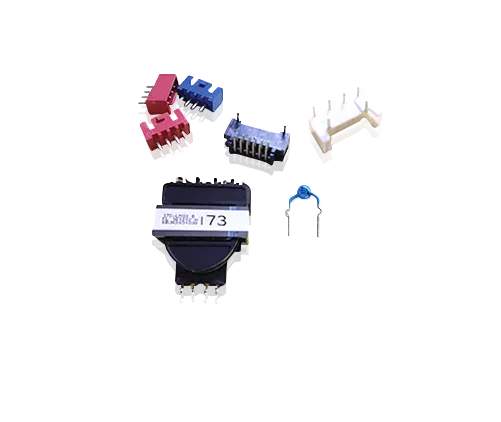
Odd-form components are non-standard parts that deviate from typical surface-mount or through-hole components. They often have irregular shapes, large sizes, or unique pin configurations, making them incompatible with automated pick-and-place machines or wave soldering systems. Examples include bulky electrolytic capacitors, high-power connectors, or custom heatsinks. These components are common in industries like automotive, aerospace, and industrial electronics, where specialized functionality is required.
The challenge with odd-form components lies in their diversity. A single PCB may include components with varying thermal masses, lead materials, or placement requirements, complicating the soldering process. For instance, a large connector with thick pins may require more heat to form a reliable joint, while nearby surface-mount components risk damage from excessive heat. According to industry standards like IPC-A-610, solder joints for odd-form components must meet strict criteria for wetting, fillet shape, and electrical continuity, making quality control paramount.
Challenges in Hand Soldering Odd-Form Components
Hand soldering odd-form components presents unique challenges that can affect quality if not addressed:
1. Thermal Management: Odd-form components often have high thermal mass, requiring prolonged heat application to achieve proper solder flow. For example, a large connector may need a soldering iron set to 350-400°C, compared to 300-350°C for standard through-hole components. Overheating can damage nearby components or the PCB substrate, while underheating can result in cold joints with poor mechanical strength.
2. Component Placement: Odd-form components may have irregular pin spacing or require precise alignment to avoid stress on solder joints. Misalignment can lead to tombstoning or insufficient solder coverage, reducing reliability.
3. Operator Variability: Hand soldering relies heavily on the skill of the operator. Inconsistent techniques, such as varying soldering times or improper flux application, can lead to defects. A 1993 study by the U.S. Department of Energy found that operator skill was one of the top factors influencing solder joint quality in hand-soldered assemblies.
4. Solderability Issues: Odd-form components may use materials with poor solderability, such as nickel-plated pins or oxidized surfaces. These require pre-tinning or specialized fluxes to ensure proper wetting, adding complexity to the process.
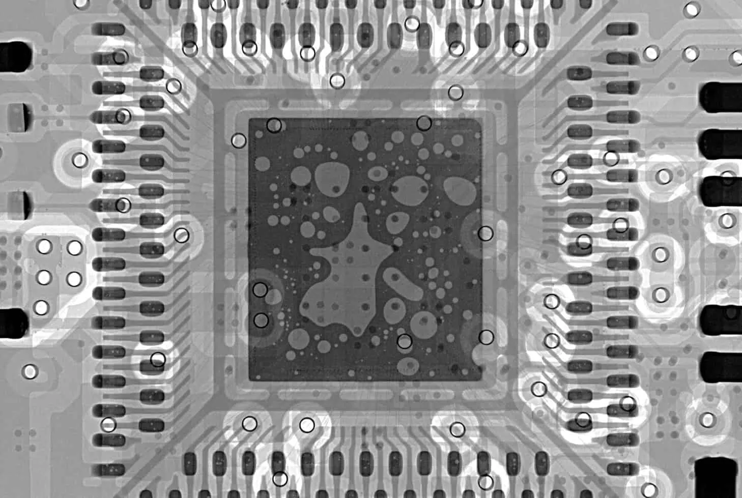
5. Inspection Difficulty: The irregular shapes of odd-form components can obscure solder joints, making visual inspection challenging. Defects like voids or insufficient solder may go unnoticed without advanced tools like X-ray imaging.
Addressing these challenges requires a combination of skilled techniques, proper tools, and rigorous quality control processes.
Best Practices for Hand Soldering Odd-Form Components
To achieve high-quality solder joints for odd-form components, we recommend the following best practices, grounded in industry standards and practical experience:
1. Pre-Tinning Components and Pads
Pre-tinning - applying a thin layer of solder to component leads and PCB pads before soldering - enhances solderability and reduces the risk of defects. For odd-form components with large or oxidized leads, pre-tinning is critical. Use a rosin-based, mildly activated (RMA) flux to clean surfaces and promote wetting. A study on lead-free soldering found that pre-tinning with 100% tin coating reduced void formation in through-hole joints by up to 30% compared to untreated leads.
2. Select the Right Soldering Tools
Choosing the appropriate soldering iron and tip is essential for odd-form components. For large components, use a high-wattage iron (60-100W) with a wide chisel or blade tip to transfer sufficient heat. For example, a 3mm chisel tip is ideal for soldering a connector with 2mm-thick pins. For precision work, such as soldering fine leads near sensitive components, a conical tip with a 0.5mm diameter ensures accuracy. Temperature control is critical - set the iron to 350-400°C for lead-free solder and 300-350°C for lead-based solder to balance effective melting with component safety.
3. Optimize Flux Application
Flux removes oxides and ensures proper solder flow, but excessive or incorrect flux can cause residue buildup or corrosion. No-clean flux is ideal for applications where post-soldering cleaning is impractical, while water-soluble flux (OA) is better for high-reliability boards requiring thorough cleaning. Apply flux sparingly using a brush or syringe to avoid pooling, which can lead to solder beading or bridges.
4. Control Soldering Time and Temperature
Soldering time should be kept to 1-2 seconds per joint to prevent thermal damage. For odd-form components with high thermal mass, use a preheating station to raise the board temperature to 100-150°C before soldering, reducing the time needed for the iron to achieve a proper joint. This technique minimizes thermal shock, which can crack the PCB laminate or damage sensitive components.
5. Train Operators for Consistency
Operator training is critical for reducing variability. Implement training programs aligned with IPC standards, such as IPC J-STD-001, which covers hand soldering techniques for high-reliability applications. Regular retraining and certification ensure operators maintain consistent techniques, such as applying the soldering iron simultaneously to the lead and pad to achieve uniform heating.
Quality Control Techniques for Hand Soldering
Quality control is the backbone of reliable hand soldering. The following techniques help identify and prevent defects in odd-form component assemblies:
1. Visual Inspection
Visual inspection, often aided by a magnifying glass or microscope, is the first line of defense. Check for:
- Proper Wetting: Solder should form a smooth, concave fillet around the lead and pad, with no gaps or irregularities.
- No Solder Bridges: Ensure solder does not connect adjacent pads, which can cause short circuits.
- No Cold Joints: Look for dull, grainy joints, which indicate insufficient heat or poor solder flow.
- No Solder Beads: Small solder balls can cause short circuits or signal interference, especially in high-frequency circuits.
2. Automated Optical Inspection (AOI)
For complex boards, AOI systems use high-resolution cameras to detect defects like solder bridges or insufficient solder. These systems are particularly useful for odd-form components with obscured joints, achieving detection rates of up to 95% for common defects.
3. X-Ray Inspection
X-ray imaging is essential for inspecting hidden joints, such as those under large connectors or transformers. It reveals voids, cracks, or incomplete solder fill, which can reduce joint strength by up to 20% in high-reliability applications.
4. Functional Testing
After soldering, perform electrical testing to verify continuity and functionality. For example, measure the resistance of solder joints (typically <0.1 ohms for a good joint) to ensure reliable electrical connections. In high-frequency circuits, test for signal integrity to confirm that solder joints do not introduce impedance mismatches, which can degrade performance at frequencies above 1 GHz.
5. Statistical Process Control (SPC)
Implement SPC to monitor soldering quality over time. Track defect rates, such as cold joints or solder bridges, and use control charts to identify trends. For instance, a defect rate above 2% may indicate issues with operator technique or material quality, prompting corrective action.
Common Defects and How to Address Them
Despite best efforts, defects can occur during hand soldering. Here are common issues with odd-form components and their solutions:
- Cold Joints: Caused by insufficient heat or poor flux application. Reheat the joint with proper solder and flux, ensuring the iron contacts both the lead and pad for 1-2 seconds.
- Solder Bridges: Result from excessive solder or improper iron removal. Use desoldering braid to remove excess solder, then re-solder with minimal solder volume.
- Tombstoning: Occurs when uneven heating lifts one side of a component. Adjust component placement and preheat the board to ensure uniform heating.
- Voids: Caused by trapped gas or insufficient solder flow. Apply additional flux and reheat to fill gaps, ensuring the solder fully wets the joint.
By addressing these defects promptly, engineers can maintain high-quality assemblies that meet industry standards.
How ALLPCB Supports Hand Soldering Excellence
For engineers tackling the complexities of hand soldering odd-form components, partnering with a reliable PCB manufacturer can make all the difference. At ALLPCB, we provide advanced manufacturing and quick-turn prototyping services tailored to the needs of specialized assemblies. Our global logistics ensure fast delivery of high-quality PCBs, while our Design for Manufacturability (DFM) reviews help identify potential soldering issues early, such as improper pad sizes or thermal profiles. Whether you're prototyping a new design with odd-form components or scaling production for high-reliability applications, our end-to-end solutions streamline the process, ensuring precision and consistency.
Conclusion
Hand soldering odd-form components requires a blend of skill, precision, and robust quality control to achieve reliable, high-performance PCB assemblies. By addressing challenges like thermal management, operator variability, and solderability issues, and by implementing best practices such as pre-tinning, proper tool selection, and rigorous inspection, engineers can minimize defects and ensure long-term reliability. Quality control techniques, from visual inspection to X-ray imaging and statistical process control, provide the tools needed to catch and correct issues early. At ALLPCB, we're committed to supporting engineers with the resources and expertise needed to excel in this critical process, delivering PCBs that meet the highest standards of quality and performance.


