 ALLPCB


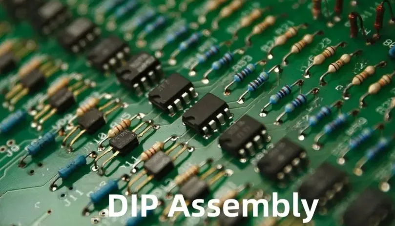
In the world of electronics manufacturing, precision is everything. One critical process that often goes unnoticed but plays a vital role in ensuring a reliable assembly is component lead forming. Whether you're working with axial or radial components, mastering lead forming techniques in leaded assembly can make or break the quality of your printed circuit board (PCB). In this blog, we'll dive deep into the essentials of component lead forming, explore best practices for leaded assembly, and cover techniques like axial lead forming, radial lead forming, as well as the use of lead bending tools and lead cutting best practices. By the end, you'll have actionable insights to improve your assembly process and achieve consistent, high-quality results.
What Is Component Lead Forming and Why Does It Matter?
Component lead forming is the process of shaping the leads (or wires) of electronic components to fit specific mounting requirements on a PCB. This is a crucial step in leaded assembly, where components with leads—such as resistors, capacitors, and diodes—are inserted into holes on the board and soldered in place. Properly formed leads ensure secure mounting, prevent damage to components, and maintain electrical reliability.
Without precise lead forming, you risk issues like poor connections, mechanical stress on components, or even short circuits. For instance, if a lead is too long, it might touch another component or trace, causing a short. If it's too short, it may not reach through the board for proper soldering. Mastering component lead forming is essential for both manual and automated assembly processes, ensuring efficiency and durability in your final product.
Types of Leads: Axial vs. Radial Components
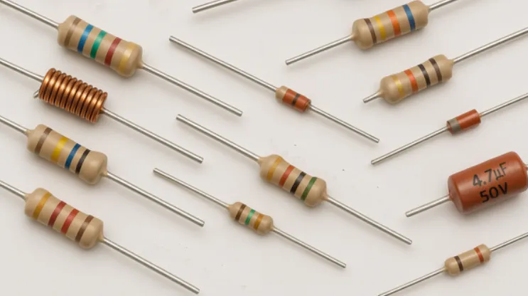
Before diving into techniques, let's clarify the two main types of components you'll encounter in leaded assembly: axial and radial. Understanding their differences is key to applying the right forming methods.
- Axial Components: These have leads that extend from both ends of the component body, like resistors and some diodes. The leads are aligned along the same axis, and they often need to be bent to fit into PCB holes that are spaced apart.
- Radial Components: These have leads that extend from one side of the component body, such as electrolytic capacitors. The leads are parallel to each other and typically require less bending but precise alignment for insertion.
Each type demands specific approaches for forming, which we'll cover in detail with axial lead forming and radial lead forming techniques.
Axial Lead Forming: Techniques and Best Practices
Axial lead forming is one of the most common processes in leaded assembly, as axial components are widely used in electronics. The goal is to bend the leads so they align perfectly with the PCB holes while avoiding damage to the component.
Steps for Axial Lead Forming
- Measure the Hole Spacing: Before bending, check the distance between the holes on your PCB where the component will be placed. This spacing typically ranges from 0.1 inches (2.54 mm) to 0.5 inches (12.7 mm) for standard through-hole designs.
- Use the Right Tool: Avoid bending leads with your fingers, as this can lead to inconsistent results or damage. Instead, use specialized lead bending tools like pliers with rounded edges or dedicated lead formers that create uniform bends without stressing the lead.
- Bend at a Safe Distance: Make the bend at least 1-2 mm away from the component body to prevent cracking or damaging the internal structure. For example, a typical 1/4-watt resistor can handle a bend radius of about 0.8 mm without risk.
- Create a 90-Degree Bend: For most axial components, bend the leads to a 90-degree angle to fit through the PCB holes. Ensure both leads are bent symmetrically for a clean fit.
- Trim Excess Length: After insertion, trim the leads to a length of about 1-2 mm beyond the PCB surface using precision cutters. This ensures there's enough lead for soldering without excess that could cause shorts.
Best Practices for Axial Lead Forming
- Always use a forming tool or jig for consistency, especially in high-volume production.
- Avoid sharp bends that can weaken the lead; aim for a smooth radius.
- Handle components gently to prevent mechanical stress, as excessive force can crack ceramic or glass bodies in some axial components.
Radial Lead Forming: Precision for Parallel Leads
Radial lead forming is often simpler than axial forming since the leads are already aligned parallel to each other. However, precision is still critical to ensure the component sits flush against the PCB and the leads fit into the holes without stress.
Steps for Radial Lead Forming
- Check Lead Spacing: Measure the distance between the leads and compare it to the PCB hole spacing. Radial components often have a standard pitch, such as 5 mm or 10 mm, which should match the board design.
- Adjust if Needed: If the spacing doesn't match, gently bend the leads using a small pair of pliers or a lead forming tool. Make small adjustments to avoid stressing the component body.
- Ensure Flush Mounting: Radial components should sit flat against the PCB. If the leads are too long, trim them slightly before insertion to achieve the correct height (typically 2-3 mm above the board after soldering).
- Insert and Secure: Push the leads through the holes and ensure the component is stable before soldering. Avoid excessive force during insertion to prevent bending or breaking the leads.
Best Practices for Radial Lead Forming
- Minimize bending for radial components to reduce stress on the leads and body.
- Use a lead forming jig if dealing with large quantities to maintain uniformity.
- Double-check polarity for components like electrolytic capacitors, as incorrect placement can lead to circuit failure.
Essential Lead Bending Tools for Precision
Using the right lead bending tools can significantly improve the quality and efficiency of your lead forming process. Here are some must-have tools for both manual and automated assembly:
- Needle-Nose Pliers: Ideal for manual bending of axial and radial leads. Choose pliers with smooth, rounded tips to avoid nicking or scoring the leads.
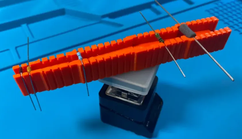
- Lead Forming Jigs: These are templates or fixtures designed to create consistent bends at specific angles and distances. They're especially useful for axial components in batch production.
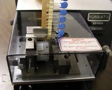
- Automated Lead Formers: For high-volume manufacturing, automated machines can form and cut leads with precision, handling thousands of components per hour. These machines often support customizable settings for different component sizes and pitches.
- Precision Cutters: After forming and insertion, use flush cutters to trim excess lead length. Look for cutters with a fine tip to access tight spaces on densely populated PCBs.
Investing in quality tools not only saves time but also reduces the risk of damaging components during component lead forming. For example, a well-designed lead former can achieve bend accuracy within 0.1 mm, ensuring perfect alignment every time.
Lead Cutting Best Practices for a Clean Finish
Once leads are formed and components are inserted, trimming excess length is the final step. Following lead cutting best practices ensures a professional finish and prevents issues during soldering or operation.
- Cut After Insertion: Always trim leads after the component is securely placed in the PCB to avoid misalignment.
- Leave Adequate Length: Cut leads to a length of 1-2 mm beyond the PCB surface. This provides enough material for soldering without risking shorts or interference with nearby components.
- Use Sharp Cutters: Dull blades can crush or deform leads, leading to poor solder joints. Use sharp, precision flush cutters for a clean cut every time.
- Angle the Cut: Trim at a slight angle (about 45 degrees) to create a pointed tip, which can improve solder flow during assembly.
- Avoid Flying Debris: Cut leads over a tray or use a tool with a built-in catch to prevent small metal clippings from scattering across your workspace or PCB, as these can cause shorts.
Proper cutting not only enhances the aesthetics of your board but also contributes to its reliability. For instance, leaving leads too long on a densely packed board can increase the risk of short circuits by up to 15%, according to industry studies on assembly defects.
Common Challenges in Leaded Assembly and How to Overcome Them
Even with the best techniques, leaded assembly can present challenges. Here are some common issues and solutions to keep your process smooth:
- Component Damage: Excessive force during bending can crack or break components. Always use tools designed for lead forming and handle components with care.
- Inconsistent Bends: Manual bending often leads to uneven results. Use a jig or automated former for uniformity, especially in larger production runs.
- Lead Stress: Bending too close to the component body can weaken the lead or internal connections. Maintain a safe distance (1-2 mm) from the body during forming.
- Short Circuits from Cuttings: Small metal clippings from trimming can cause shorts if not managed. Use a debris catch or vacuum to keep your workspace clean.
Manual vs. Automated Lead Forming: Which Is Right for You?
Deciding between manual and automated component lead forming depends on your production volume and budget. Here's a quick comparison:
| Aspect | Manual Lead Forming | Automated Lead Forming |
|---|---|---|
| Cost | Low (basic tools cost $10-50) | High (machines start at $1,000+) |
| Speed | Slow (10-20 components per minute) | Fast (hundreds to thousands per hour) |
| Precision | Variable, depends on skill | High, consistent results |
| Best For | Prototyping, small batches | High-volume production |
For hobbyists or small-scale projects, manual tools are often sufficient. However, if you're scaling up production, investing in automated equipment can save time and ensure consistency in leaded assembly.
Conclusion: Mastering Lead Forming for Reliable Assembly
Component lead forming is a fundamental skill in leaded assembly that directly impacts the quality and reliability of your electronic projects. By understanding the nuances of axial lead forming and radial lead forming, using the right lead bending tools, and adhering to lead cutting best practices, you can achieve professional results every time. Whether you're working manually on a prototype or automating a large-scale production line, precision in component lead forming is non-negotiable.
Take the time to refine your techniques, invest in quality tools, and follow the best practices outlined in this guide. With these steps, you'll not only improve your assembly process but also ensure your PCBs perform reliably in the field. Let's bend the rules of assembly—without breaking them—and build electronics that stand the test of time.


