ALLPCB


Signal amplification is a cornerstone of modern electronics, enabling everything from audio systems to wireless communication. At the heart of this process are active components like transistors and operational amplifiers (op-amps), which boost weak signals for better performance. In this comprehensive guide, we’ll explore the role of active components in signal amplification, diving into design techniques and best practices for transistor amplifier design, op-amp circuits, signal boosting with active components, and low noise amplifier design. Whether you're an engineer or a hobbyist, this post will provide actionable insights to enhance your circuit designs.
Understanding Active Components in Signal Amplification
Active components are electronic elements that can amplify signals by injecting energy into a circuit, unlike passive components like resistors or capacitors that only store or dissipate energy. In signal amplification, active components such as transistors and op-amps are essential for increasing the amplitude of weak signals without significant distortion. These components are widely used in applications like audio equipment, radio frequency (RF) systems, and sensor interfaces.
Signal amplification is critical when dealing with low-power signals that need to drive larger loads or travel long distances. By using active components, you can ensure that the signal remains strong and clear. In the sections below, we’ll break down the key design techniques and best practices to achieve optimal results in your projects.
What Are Active Components and Why Do They Matter?
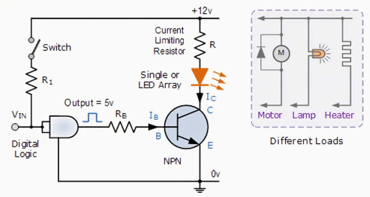
Active components include devices like transistors (BJTs and FETs) and integrated circuits such as op-amps. These components require an external power source to operate and can control or amplify electrical signals. Unlike passive components, which can only reduce signal strength, active components add energy to the system, making them ideal for signal boosting with active components.
For instance, in a transistor amplifier design, a small input signal can control a larger output current, effectively amplifying the signal. Similarly, op-amp circuits provide high gain and flexibility, allowing engineers to design complex systems with minimal components. Understanding how these components work is the first step to mastering amplification design.
Key Design Techniques for Transistor Amplifier Design
Transistor amplifiers are fundamental in signal boosting, offering a simple yet effective way to increase signal strength. Here are some essential design techniques to consider for transistor amplifier design:
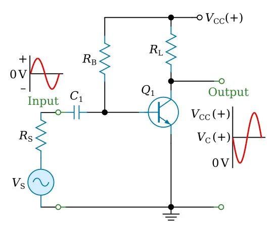
- Biasing for Stability: Proper biasing ensures the transistor operates in the active region, where it can amplify signals linearly. For a common-emitter NPN transistor amplifier, a typical biasing setup might use a voltage divider with resistors of 10 kΩ and 2.2 kΩ to set the base voltage at approximately 1.2V, assuming a 12V supply.
- Gain Control: The gain of a transistor amplifier depends on the load resistor and the transistor’s current gain (β). For example, with a load resistor of 1 kΩ and a β of 100, you can calculate the voltage gain using the formula Av = -Rc/Re, where Rc is the collector resistor and Re is the emitter resistor.
- Frequency Response: Use coupling capacitors (e.g., 10 μF) to block DC while allowing AC signals to pass, ensuring the amplifier works within the desired frequency range, such as 20 Hz to 20 kHz for audio applications.
By carefully selecting component values and configurations, you can tailor a transistor amplifier to meet specific needs, whether for audio or RF applications.
Mastering Op-Amp Circuits for Versatile Signal Boosting
Operational amplifiers, or op-amps, are incredibly versatile active components used in a wide range of signal processing tasks. Op-amp circuits can be configured for various amplification needs, from simple voltage followers to complex filters. Here are some best practices for designing effective op-amp circuits:
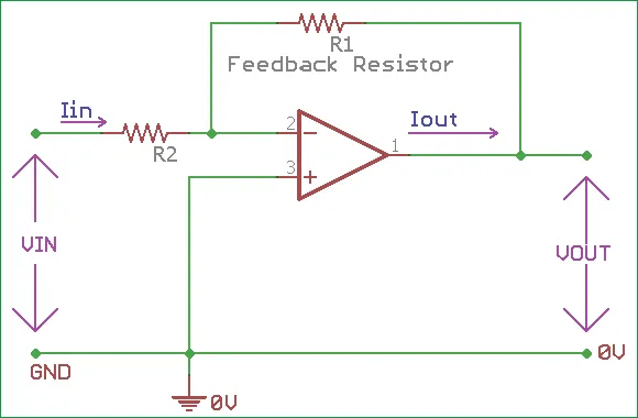
- Inverting Amplifier Configuration: In an inverting op-amp circuit, the gain is determined by the ratio of the feedback resistor (Rf) to the input resistor (Rin), given by Av = -Rf/Rin. For a gain of 10, you might choose Rf = 10 kΩ and Rin = 1 kΩ.
- Non-Inverting Amplifier: For applications where phase inversion isn’t desired, use a non-inverting configuration with a gain of 1 + (Rf/Rin). This setup is ideal for buffering signals with minimal distortion.
- Power Supply Considerations: Ensure the op-amp operates within its specified voltage range (e.g., ±15V for many standard op-amps) to avoid clipping or damage. Decoupling capacitors (e.g., 0.1 μF) near the power pins can reduce noise.
Op-amps are particularly useful because of their high input impedance and low output impedance, making them perfect for interfacing with sensors or other low-power signal sources.
Signal Boosting with Active Components: Practical Tips
Signal boosting with active components is a critical skill in electronics design. Whether using transistors or op-amps, the goal is to increase signal strength without introducing noise or distortion. Here are some practical tips to achieve effective signal boosting:
- Match Impedance: Ensure the input and output impedance of your amplifier matches the source and load for maximum power transfer. For instance, in RF systems, a 50-ohm impedance match is often standard.
- Use Feedback Networks: Negative feedback in op-amp circuits or transistor designs can stabilize gain and reduce distortion. A feedback resistor of 5 kΩ in an op-amp circuit can help maintain consistent performance.
- Avoid Overloading: Ensure the active component isn’t driven beyond its limits. For example, check the maximum collector current of a transistor (often around 100 mA for small-signal types) to prevent overheating.
By following these tips, you can create robust designs that deliver clean, amplified signals for various applications.
Low Noise Amplifier Design: Minimizing Interference
Low noise amplifier (LNA) design is crucial in applications where signal integrity is paramount, such as in RF communication or medical devices. LNAs are designed to amplify weak signals while adding minimal noise. Here are some best practices for low noise amplifier design:
- Choose Low-Noise Components: Select transistors or op-amps with low noise figures. For example, certain field-effect transistors (FETs) have noise figures as low as 0.5 dB at 1 GHz, ideal for RF applications.
- Optimize Biasing: Operate the active component at a bias point that minimizes noise. For a BJT, this might mean setting the collector current to 1 mA to balance gain and noise performance.
- Shielding and Layout: Use proper PCB layout techniques, such as grounding planes and short trace lengths, to reduce electromagnetic interference. Place sensitive components away from high-current paths.
- Bandwidth Consideration: Design the LNA to operate within a specific bandwidth to avoid amplifying unwanted noise. For instance, a narrowband LNA for a 2.4 GHz Wi-Fi signal might use tuned circuits with inductors and capacitors to filter out irrelevant frequencies.
Effective LNA design ensures that weak signals are amplified cleanly, which is essential for high-sensitivity applications.
Best Practices for Designing Amplification Circuits with Active Components
To wrap up, let’s summarize some overarching best practices that apply to all types of amplification circuits using active components:
- Start with Simulation: Use circuit simulation software to test your design before building a prototype. This can help identify issues like improper biasing or excessive noise early on.
- Component Selection: Choose components based on the specific requirements of your application. For high-frequency designs, ensure transistors have a sufficient transition frequency (fT), often in the range of 300 MHz or higher for RF.
- Thermal Management: Active components generate heat during operation. Ensure proper heat dissipation with heat sinks or adequate spacing on the PCB, especially for power amplifiers where currents can exceed 1A.
- Testing and Iteration: Build and test your circuit in stages, measuring key parameters like gain, noise figure, and distortion. Use an oscilloscope to verify signal integrity at each stage.
By adhering to these practices, you can create reliable and efficient amplification circuits tailored to your needs.
Common Challenges and How to Overcome Them
Designing amplification circuits isn’t without challenges. Here are a few common issues and solutions:
- Signal Distortion: This often results from improper biasing or overloading. Double-check bias points and ensure input signals are within the linear range of the amplifier. For op-amps, ensure the slew rate (e.g., 0.5 V/μs for basic models) matches the signal speed.
- Noise Issues: External noise can degrade performance. Use shielding, proper grounding, and low-noise components to minimize interference.
- Power Supply Noise: Ripple or noise from the power supply can affect amplification. Add bypass capacitors (e.g., 10 μF and 0.1 μF in parallel) near active components to filter out unwanted noise.
Addressing these challenges during the design phase can save time and improve the final performance of your circuit.
Conclusion: Building Better Amplifiers with Active Components
Active components like transistors and op-amps are indispensable in signal amplification, offering powerful ways to boost weak signals for a variety of applications. By mastering transistor amplifier design, op-amp circuits, signal boosting with active components, and low noise amplifier design, you can create circuits that are both efficient and reliable. Focus on proper biasing, impedance matching, noise reduction, and thorough testing to ensure optimal performance.
At ALLPCB, we’re committed to supporting your electronics projects with high-quality PCB manufacturing and assembly services. Whether you’re prototyping a new amplifier design or scaling up production, our expertise can help bring your ideas to life. Dive into these design techniques and best practices to elevate your next project, and let us assist with the fabrication process to ensure precision and quality.