ALLPCB


If you're looking for practical advice on soldering PCB components for a solar inverter, you're in the right place. This guide offers actionable tips and techniques to help you achieve strong, reliable solder joints for your electronics assembly projects. Whether you're a beginner or a seasoned technician, we'll walk you through the essentials of soldering solar inverter PCB components with precision and care. From choosing the right tools to mastering techniques, this hands-on guide covers everything you need to know to ensure your solar inverter PCB performs efficiently.
Introduction to Soldering Solar Inverter PCB Components
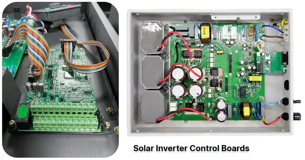
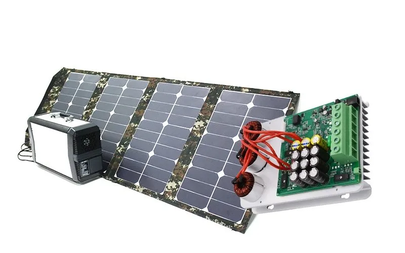
Solar inverters are critical devices that convert DC power from solar panels into AC power for household or industrial use. At the heart of these inverters lies the printed circuit board (PCB), a complex assembly of electronic components that must be soldered with accuracy to ensure functionality and durability. Soldering PCB components for solar inverters can be challenging due to the mix of through-hole and surface-mount devices (SMDs), as well as the need for high reliability under varying temperatures and electrical loads.
In this comprehensive guide, we'll share soldering tips and techniques tailored specifically for solar inverter PCBs. Our goal is to help you avoid common pitfalls like cold solder joints or overheating components, while ensuring your electronics assembly meets industry standards. Let's dive into the world of soldering and explore how to create robust connections for your solar inverter projects.
Why Soldering Matters for Solar Inverter PCBs
Soldering is more than just joining components to a board; it's about creating strong electrical and mechanical connections that can withstand the demands of a solar inverter. These devices often operate in harsh environments, with temperature fluctuations and high current loads that can stress solder joints. Poor soldering can lead to failures like intermittent connections, increased resistance, or even complete circuit breakdowns.
For instance, a typical solar inverter might handle currents up to 10-20 amps, depending on the system size. A weak solder joint could introduce resistance as high as 0.1 ohms, leading to voltage drops and heat buildup that degrade performance. By mastering soldering techniques, you ensure that your solar inverter PCB delivers consistent power conversion with minimal energy loss.
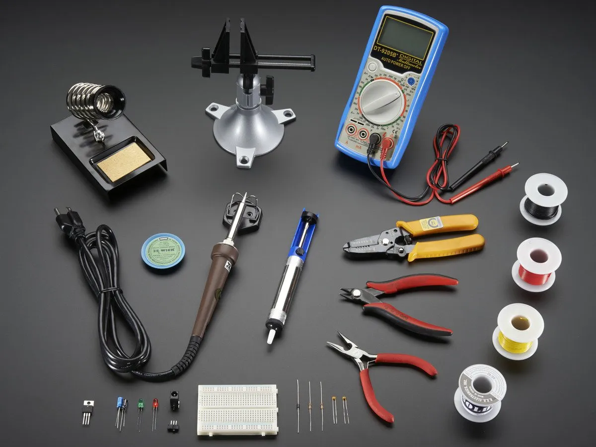
Essential Tools for Soldering Solar Inverter PCB Components
Before you start soldering, having the right tools is crucial for achieving professional results. Here's a list of must-have equipment for electronics assembly:
- Soldering Iron or Station: Choose a temperature-controlled soldering iron with a fine tip (1mm or smaller) for precision work on small components. A power rating of 25-40 watts is ideal for most PCB tasks.
- Solder Wire: Use lead-free solder with a rosin core, typically with a diameter of 0.5-1mm. A common alloy is Sn96.5Ag3.0Cu0.5, which melts at around 217°C (422°F).
- Flux: Flux helps clean surfaces and improve solder flow. Use a no-clean flux pen for convenience on solar inverter PCBs.
- Desoldering Tools: A desoldering pump or braid is essential for correcting mistakes or removing components.
- Tweezers and Magnifier: Precision tweezers help place small SMD components, while a magnifying glass or loupe ensures you spot defects in solder joints.
- Cleaning Supplies: Isopropyl alcohol (90% or higher) and a brush remove flux residue after soldering.
Preparation Tips Before Soldering
Preparation is key to successful soldering. Taking the time to set up your workspace and components can save you from costly errors during electronics assembly.
- Clean the PCB and Components: Use isopropyl alcohol and a brush to remove dust, grease, or oxidation from the PCB pads and component leads. Clean surfaces ensure better solder adhesion.
- Organize Components: Sort components by type and value to avoid mistakes. For solar inverter PCBs, you might deal with resistors, capacitors, MOSFETs, and microcontrollers—keep them labeled and accessible.
- Check Polarity: Many components like diodes and electrolytic capacitors have polarity. Double-check their orientation on the PCB before soldering to prevent damage.
- Set the Soldering Iron Temperature: For lead-free solder, set your iron to 300-350°C (572-662°F). Too high a temperature can damage components, while too low can result in cold joints.
Soldering Techniques for Solar Inverter PCB Components
Now that you're prepared, let's explore the core soldering techniques that will help you achieve reliable connections on your solar inverter PCB. We'll cover both through-hole and surface-mount soldering methods commonly used in electronics assembly.
1. Soldering Through-Hole Components
Through-hole components, such as large capacitors or connectors, are common in solar inverter PCBs due to their ability to handle high power. Follow these steps for a secure connection:
- Insert the component leads through the designated holes on the PCB.
- Bend the leads slightly on the underside to hold the component in place.
- Apply a small amount of flux to the pad and lead for better solder flow.
- Heat the pad and lead simultaneously with the soldering iron tip for 2-3 seconds, then apply solder wire to the joint. The solder should flow smoothly, forming a shiny, cone-shaped joint.
- Remove the iron and let the joint cool naturally—do not blow on it, as this can cause cracks.
- Trim excess leads with flush cutters for a neat finish.
Image Placement Suggestion: Add an image here showing a through-hole component being soldered to a PCB. ALT Text: "Soldering through-hole component on solar inverter PCB"
2. Soldering Surface-Mount Devices (SMDs)
SMDs, like small resistors, capacitors, and ICs, are increasingly common in modern solar inverter designs due to their compact size. Soldering these tiny components requires precision:
- Apply a thin layer of solder paste or flux to the PCB pads where the SMD will be placed.
- Using tweezers, position the component on the pads, aligning it with the markings on the PCB.
- Heat one pad with the soldering iron and apply a small amount of solder to create a tack joint to hold the component.
- Solder the remaining pads, ensuring the solder flows evenly without bridging adjacent pads.
- Inspect the joint under magnification to confirm there are no cold joints or excess solder.
For ICs with multiple pins, consider using the drag soldering technique. Apply flux to all pads, add solder to the iron tip, and drag it across the pins to create uniform joints quickly.
3. Avoiding Common Soldering Mistakes
Even experienced technicians can make errors during soldering. Here are common issues to watch for on solar inverter PCBs:
- Cold Solder Joints: These occur when the solder doesn't fully melt, resulting in a dull, grainy appearance. They can cause intermittent connections. Fix them by reheating the joint and adding fresh solder.
- Overheating Components: Prolonged heat can damage sensitive parts like microcontrollers or transistors. Limit soldering time to 3-5 seconds per joint.
- Solder Bridges: Excess solder can connect adjacent pads, causing shorts. Use desoldering braid to remove unwanted solder.
Special Considerations for Solar Inverter PCBs
Solar inverter PCBs often include high-power components like MOSFETs and inductors that require extra care during soldering. These components handle significant current and voltage—sometimes up to 600V or more in larger systems—so robust solder joints are non-negotiable.
Temperature Management: High-power components can generate heat, so ensure your solder joints are mechanically strong to prevent cracking under thermal stress. Use a soldering iron with sufficient wattage to heat large pads quickly without overheating nearby components.
Ground Planes: Many solar inverter PCBs have large ground planes to manage heat and reduce noise. Soldering to these areas can be tricky due to their heat dissipation. Preheat the area with a hot air gun if needed, then apply solder to ensure a solid connection.
Image Placement Suggestion: Include an image here of a solar inverter PCB with high-power components soldered in place. ALT Text: "High-power components soldered on solar inverter PCB"
Post-Soldering Inspection and Testing
After soldering, inspecting and testing your work is crucial to ensure the solar inverter PCB functions as intended. Follow these steps:
- Visual Inspection: Use a magnifying glass to check for shiny, smooth solder joints. Look for cracks, bridges, or unsoldered pins.
- Clean the Board: Remove flux residue with isopropyl alcohol and a brush to prevent corrosion over time.
- Continuity Test: Use a multimeter to verify connections between components and pads. Ensure there are no shorts between adjacent traces.
- Power-Up Test: Connect the PCB to a low-voltage power source initially (e.g., 5V if applicable) to check for basic functionality before applying full operational voltage.
Advanced Soldering Tips for Professionals
If you're an experienced engineer working on complex solar inverter PCBs, consider these advanced soldering tips to elevate your electronics assembly skills:
- Hot Air Rework Stations: For densely populated boards or when replacing SMDs, a hot air station allows precise heat application without touching components. Set the temperature to around 300°C (572°F) and use a small nozzle for accuracy.
- Solder Paste and Reflow: For mass assembly or intricate designs, apply solder paste to pads and use a reflow oven or hot air to melt it uniformly across all components. This method is ideal for SMD-heavy solar inverter PCBs.
- Thermal Relief Pads: When soldering to large copper areas, thermal relief pads (spoked connections) help manage heat distribution, making soldering easier and reducing the risk of cold joints.
Troubleshooting Soldering Issues on Solar Inverter PCBs
Even with careful soldering, issues can arise. Here's how to troubleshoot common problems:
- Component Not Functioning: Check for poor solder joints or incorrect component orientation. Reflow the joint or replace the component if damaged by heat.
- High Resistance in Circuit: Measure resistance across solder joints with a multimeter. Values above 0.01 ohms may indicate a weak joint—reheat and add fresh solder.
- Intermittent Connections: Flex the PCB slightly to see if connections fail. This often points to cracked solder joints, which can be fixed by reflowing with flux.
Conclusion: Mastering Soldering for Solar Inverter PCBs
Soldering solar inverter PCB components is a skill that combines precision, patience, and the right techniques. By following the soldering tips and tricks outlined in this guide, you can create reliable, high-performing electronics assemblies that power solar energy systems effectively. From selecting the proper tools to mastering through-hole and SMD soldering techniques, every step contributes to the durability and efficiency of your solar inverter PCB.
Whether you're working on a small residential inverter or a large industrial system, the principles of good soldering remain the same: prepare thoroughly, apply heat carefully, and inspect diligently. With practice, you'll build the confidence to tackle even the most complex PCB designs, ensuring your solar inverter projects shine bright for years to come.