 ALLPCB


In the fast-paced world of electronics, designing high-speed printed circuit boards (PCBs) is a complex task that demands precision and expertise. One of the most critical aspects of this process is selecting the right electromechanical components. These components, such as connectors and relays, play a vital role in ensuring PCB signal integrity, minimizing electromagnetic interference (EMI), and reducing signal loss. This comprehensive guide will walk you through the essential electromechanical component selection criteria for high-speed PCB design, covering everything from high-frequency connectors to low-inductance relays. Whether you're a seasoned engineer or new to PCB design, this article offers actionable insights to optimize your designs for performance and reliability.
Why Electromechanical Component Selection Matters in High-Speed PCB Design
High-speed PCBs operate at frequencies where even small design flaws can lead to significant issues like signal degradation or EMI. Electromechanical components are often the bridge between the PCB and external systems, making their selection crucial for maintaining performance. Poorly chosen components can introduce noise, increase signal loss, or compromise the overall system integrity. By focusing on the right electromechanical component selection criteria, you can ensure seamless data transmission, reduce interference, and achieve a robust design.
Key Criteria for Electromechanical Component Selection in High-Speed PCBs
Selecting electromechanical components for high-speed designs requires a deep understanding of several factors. Below, we break down the most important considerations to guide your decision-making process.
1. Frequency Range and High-Frequency Connectors
In high-speed PCB designs, components must support the operating frequency of the system, often in the gigahertz (GHz) range. High-frequency connectors are essential for maintaining signal quality at these speeds. Look for connectors with low insertion loss and high return loss specifications. For example, a connector rated for 10 GHz with an insertion loss of less than 0.5 dB ensures minimal signal degradation.
Additionally, consider the connector's impedance matching, typically 50 ohms for most high-speed applications. Mismatched impedance can cause signal reflections, leading to data errors. Choose connectors with tight tolerance and shielding to prevent crosstalk and EMI.
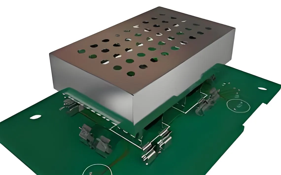
2. Low-Inductance Relays for Reduced Signal Delay
Relays are often used in high-speed systems for switching signals or power. However, standard relays can introduce parasitic inductance, which delays signal propagation and affects timing. Low-inductance relays are designed to minimize this effect, offering faster switching times and better performance in high-speed applications.
For instance, a relay with an inductance of less than 1 nH is ideal for maintaining signal timing in circuits operating at 5 GHz or higher. Check the relay's datasheet for contact resistance and switching speed, as these also impact performance. Opt for relays with gold-plated contacts to ensure low resistance and reliable operation over time.
3. Minimizing EMI in Electromechanical Components
Electromagnetic interference (EMI) is a major concern in high-speed PCB design, as it can disrupt signal integrity and cause system failures. To achieve minimizing EMI in electromechanical components, prioritize components with built-in shielding or grounding features. Connectors with metal shells or integrated EMI gaskets can significantly reduce noise coupling.
Positioning is also key. Place connectors and relays away from high-speed signal traces to avoid interference. If possible, use differential signaling near electromechanical components to cancel out common-mode noise. Finally, ensure proper grounding by connecting component shields to a solid ground plane, reducing the loop area for potential EMI pickup.
4. Signal Loss in Electromechanical Components
Signal loss is a critical issue in high-speed designs, especially when signals pass through connectors or relays. Signal loss in electromechanical components can occur due to resistance, dielectric losses, or poor contact quality. To combat this, select components with low dielectric constants and minimal contact resistance. For example, a connector with a dielectric constant below 3.5 can reduce signal attenuation at high frequencies.
Pay attention to the material used in the component. High-quality insulators like PTFE (Teflon) can lower dielectric losses compared to standard plastics. Also, ensure clean and secure connections to avoid signal degradation caused by loose contacts or corrosion over time.
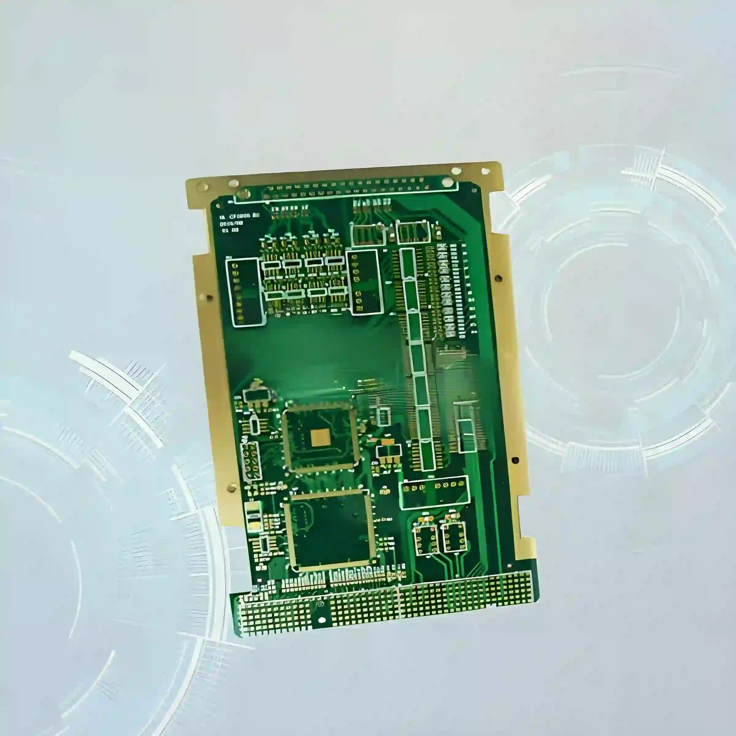
5. Mechanical Durability and Environmental Factors
High-speed PCBs often operate in demanding environments, so electromechanical components must withstand physical stress, temperature fluctuations, and humidity. Choose components with high mating cycles (e.g., connectors rated for 5000+ cycles) to ensure long-term reliability. Look for materials resistant to corrosion, such as stainless steel or gold plating, especially for outdoor or industrial applications.
Temperature ratings are equally important. A relay or connector rated for -40°C to 85°C can handle extreme conditions without degrading performance. Check for compliance with industry standards like RoHS to ensure environmental safety and compatibility.
Best Practices for High-Speed PCB Design with Electromechanical Components
Beyond component selection, how you integrate electromechanical components into your PCB layout significantly impacts performance. Here are some proven strategies to optimize your high-speed PCB design.
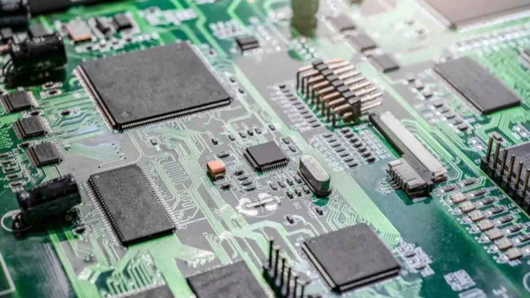
1. Optimize PCB Layout for Signal Integrity
PCB signal integrity is directly influenced by trace routing and component placement. Keep high-speed traces as short and straight as possible to reduce signal delay and reflections. Avoid placing electromechanical components near sensitive traces to prevent noise coupling. Use controlled impedance traces, maintaining a consistent 50-ohm impedance for high-frequency signals.
Incorporate solid ground planes beneath signal layers to provide a low-impedance return path. This reduces EMI and enhances signal quality. For connectors, place decoupling capacitors (e.g., 0.1 μF) close to power pins to stabilize voltage and filter noise.
2. Use Simulation Tools for Validation
Before finalizing your design, use simulation software to model signal behavior and identify potential issues. Tools can simulate signal loss, EMI, and impedance mismatches caused by electromechanical components. For example, running a time-domain reflectometry (TDR) analysis can reveal impedance discontinuities at connector interfaces, allowing you to adjust the design accordingly.
Simulations also help verify the performance of low-inductance relays under high-speed conditions. By modeling switching transients, you can ensure the relay won’t introduce unacceptable delays or noise into the system.
3. Test and Iterate for Optimal Performance
After assembling your PCB, conduct thorough testing to validate component performance. Use a vector network analyzer (VNA) to measure insertion loss and return loss at connectors. Test relays for switching speed and signal fidelity using an oscilloscope. If issues arise, iterate on component selection or layout adjustments to resolve them.
For instance, if a connector shows high signal loss at 8 GHz, consider replacing it with a model offering better high-frequency performance. Document test results to build a knowledge base for future designs, ensuring continuous improvement.
Common Challenges and How to Overcome Them
Even with careful planning, challenges can arise during electromechanical component selection for high-speed PCBs. Here are some common issues and solutions to keep your project on track.
1. Balancing Cost and Performance
High-performance components often come with a higher price tag, which can strain budgets. To balance cost and performance, prioritize critical areas of your design. For example, invest in premium high-frequency connectors for critical signal paths, while using more affordable options for less demanding connections. Compare datasheets to find components that meet your specifications without unnecessary over-specification.
2. Managing Space Constraints
High-speed PCBs often have limited space, making it challenging to place large electromechanical components. Opt for compact, surface-mount components whenever possible. If space is extremely tight, consider custom connectors or relays designed for high-density applications. Adjust your layout to accommodate critical components first, then route traces around them.
3. Addressing Compatibility Issues
Ensuring compatibility between electromechanical components and your PCB design is essential. Mismatched connectors or relays can lead to mechanical or electrical failures. Always verify pin configurations, voltage ratings, and current capacities before finalizing your selection. Cross-check with suppliers for compatibility data to avoid surprises during assembly.
Conclusion: Building High-Performance High-Speed PCBs
Selecting the right electromechanical components is a cornerstone of successful high-speed PCB design. By focusing on electromechanical component selection criteria like frequency range, inductance, EMI mitigation, and signal loss, you can create designs that deliver exceptional performance and reliability. Pairing careful selection with best practices like optimized layouts, simulations, and thorough testing ensures your PCB meets the demands of modern high-speed applications.
Whether you're working on telecommunications, automotive, or consumer electronics, mastering the selection of high-frequency connectors, low-inductance relays, and other components will set your designs apart. Use this guide as a roadmap to navigate the complexities of electromechanical integration, and build PCBs that stand up to the challenges of high-speed environments. With the right approach, you can achieve outstanding PCB signal integrity, minimize interference, and reduce signal loss in electromechanical components for unparalleled results.


