ALLPCB


Overview
EDA (Electronic Design Automation) synthesis refers to the process of converting high-level hardware description language (HDL) code into a logic netlist during integrated circuit design. Common types of synthesis include the following.
Types of EDA Synthesis
- Logic synthesis: Converts hardware functionality described in high-level languages such as Verilog or VHDL into an equivalent logic netlist. The logic synthesis stage performs logic optimization, generates placement constraints, and supports clock tree synthesis.
- Timing synthesis: Performs timing analysis and adjustments on the logic netlist to ensure the circuit meets timing requirements. Timing synthesis considers clock skew, propagation delays, and timing constraints across timing paths.
- Physical synthesis: Integrates the logic netlist with physical design (placement and routing) to produce a complete physical design database. Physical synthesis involves logic optimization, generation of placement constraints, global placement, detailed placement, and subsequent optimizations.
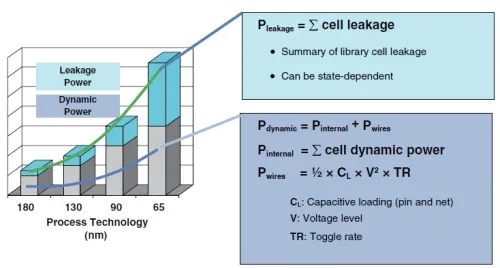
- Power optimization synthesis: Focuses on reducing power consumption during synthesis by applying techniques such as low-power logic styles and power management strategies.
These synthesis types play roles at different stages of IC design, helping engineers move from high-level descriptions to physical implementations while optimizing performance, power, and area.
Principles of Logic Synthesis
Logic synthesis converts HDL code into a logic netlist. The core process typically includes the following steps.
- Lexical and syntactic analysis: Parse the input HDL according to language syntax to build an abstract syntax tree (AST) and detect syntax errors.
- Semantic analysis: Perform semantic checks on the AST, including variable declaration checks, type checking, and signal assignments, to ensure code correctness.
- Combinational logic optimization: Apply optimization algorithms to the combinational logic. Common methods include Boolean algebra simplification, truth-table minimization, and gate-level substitutions to reduce gate count, logic depth, and delay.
- Establishing timing relationships: Use user-provided timing constraints to determine delay relationships along timing paths. Constraints can include clock periods and path-specific timing limits for later timing synthesis.
- Technology mapping: Map the optimized logic netlist to target cells or macros in a standard-cell library or predefined modules, improving reuse and reducing resource usage.
- Timing optimization: Optimize the design to meet timing targets and clock frequency goals. Techniques include delay balancing, inserting clock buffers, and optimizing clock paths.
- Netlist output: Emit the synthesized and optimized logic netlist as input for subsequent physical design stages such as placement and routing.
In summary, logic synthesis translates HDL into an equivalent logic netlist while applying a series of optimizations and transformations to meet functional, timing, and performance requirements. It enables design and verification at a high level and provides the foundation for downstream physical implementation.