 ALLPCB


Transient voltage and current disturbances are a primary cause of damage to electronic circuits and equipment. These disturbances often originate from the startup and shutdown of electrical equipment, AC grid instability, lightning strikes, and electrostatic discharge (ESD). While transient events are nearly ubiquitous, high-efficiency circuit protection devices like Transient Voltage Suppressor (TVS) diodes can effectively mitigate them.
A Transient Voltage Suppressor (TVS) diode is a protection component developed based on Zener diode technology. Its circuit symbol is identical to that of a standard Zener diode, and its physical package is similar to a regular diode. When a TVS diode is subjected to a high-energy transient pulse, it rapidly reduces its impedance (in as fast as 1 x 10-12 seconds) to absorb a large current. This clamps the voltage across its terminals to a predetermined level, thereby protecting downstream circuit components from damage.
TVS Characteristics
The I-V curve of a TVS diode, as viewed on a curve tracer, is similar to the breakdown characteristic of a standard Zener diode, showing typical PN junction avalanche behavior. However, to understand its full protective function, it is also necessary to observe its response to a large current surge on an oscilloscope.
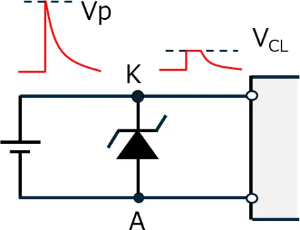
During a surge event, such as a lightning strike or overvoltage condition, the current through the TVS will rise abruptly to a peak value before decaying exponentially. In response, the voltage across the TVS rises but is clamped at the maximum clamping voltage (VC), a value slightly higher than its breakdown voltage (VBR). This clamping action protects the downstream circuitry.
TVS Parameters
- Breakdown Voltage (VBR): The voltage at which the TVS enters an avalanche breakdown state and its impedance drops sharply.
- Test Current (IT): The current at which the breakdown voltage VBR is measured. IT is typically 1 mA.
- Reverse Standoff Voltage (VRWM): The maximum rated DC operating voltage. Below this voltage, the TVS remains in a high-impedance state.
- Maximum Reverse Leakage Current (IR): The maximum current that flows through the TVS when the operating voltage VRWM is applied.
- Maximum Peak Pulse Current (IPP): The maximum surge current that the TVS can withstand, indicating its surge suppression capability.
- Maximum Clamping Voltage (VC): When the TVS is subjected to a transient pulse with a peak current of IPP, the voltage across its terminals rises from VRWM to VC and is held at that level. After the surge, as IPP decays, the voltage returns to its normal state. The ratio of VC to VBR is called the clamping factor (Cf = VC / VBR), which is typically between 1.2 and 1.4.
- Peak Pulse Power (PP): Calculated as PP = VC * IPP. Based on their peak pulse power rating, TVS diodes are commonly available in ratings such as 500 W, 600 W, 1500 W, and 5000 W. A higher PP rating means the TVS can handle a larger IPP. Conversely, for a given PP, the manageable IPP increases as VC decreases. The maximum allowable pulse power also depends on the pulse waveform, duration, and ambient temperature.
TVS diodes can withstand instantaneous peak pulse currents of several hundred amperes, with a clamping response time as fast as 1 x 10-12 seconds. Under forward bias conditions, they can also handle surge currents of 50-200 A at 25°C for 1/120 seconds. Generally, the rated pulse for a TVS is a non-repetitive pulse. In practical applications, repetitive pulses may occur. For repetitive pulses, datasheets often specify a maximum duty cycle, such as 0.01% (the ratio of pulse duration to the interval between pulses). Exceeding this can lead to cumulative heating and device failure. Circuit designers should be aware of this. TVS devices are highly reliable; even after withstanding thousands of non-repetitive high-energy pulses, their maximum power rating typically remains above 80% of the original value.
TVS diodes are primarily used for fast overvoltage protection of electronic components. They can absorb surge signals with power ratings up to several kilowatts. Their advantages include small size, high power handling, fast response, low noise, and low cost. They are widely used in various fields, including:
- Home appliances
- Electronic instruments and meters
- Precision equipment
- Computer systems
- Communication equipment
- Protection for communication ports like RS232, RS485, and CAN
- ISDN protection
- I/O ports
- IC protection
- Audio and video inputs
- AC and DC power supplies
- Noise suppression for motors and relays
How to Select a TVS Diode
- Determine the DC or continuous operating voltage of the circuit to be protected. For AC circuits, calculate the peak voltage (RMS value * 1.414).
- Select a TVS with a Reverse Standoff Voltage (VRWM) that is equal to or greater than the operating voltage determined in step 1. This ensures that the TVS draws negligible current under normal conditions. If the circuit voltage exceeds VRWM, the TVS will enter avalanche breakdown and draw significant leakage current, which can interfere with circuit operation.
- Determine the required Peak Pulse Power (PP) by analyzing the expected transient pulse waveform and duration in the circuit.
- The Maximum Clamping Voltage (VC) of the selected TVS must be lower than the maximum voltage the protected circuit can safely withstand.
- Choose between a unidirectional or bidirectional TVS. Bidirectional TVS diodes are used in AC circuits or where both positive and negative transients are expected. They can also be chosen to minimize capacitance. If the circuit only handles positive voltage levels, a unidirectional TVS is sufficient. A unidirectional TVS operates by entering reverse avalanche breakdown for a positive surge and conducting like a forward-biased diode for a negative surge. For low-capacitance circuits, a bidirectional TVS may be preferable to protect sensitive components from reverse-polarity transients.
- If the exact surge current (IPP) is known, you can use VC to verify the power rating (PP = VC * IPP). If the required power rating is uncertain, it is generally safer to choose a TVS with a higher power rating.


