 ALLPCB


Are you looking for reliable methods to create durable PCB connections using through-hole technology (THT)? Through-hole assembly remains a trusted choice for applications requiring strong mechanical bonds and high reliability. In this comprehensive guide, we’ll dive into the through-hole assembly process, explore THT soldering techniques, and share tips for wave soldering optimization, manual through-hole assembly, component lead insertion, and enhancing PCB durability. Whether you’re an engineer or a hobbyist, this blog will provide actionable insights to improve your PCB assembly projects.
What Is Through-Hole Technology and Why Does It Matter?
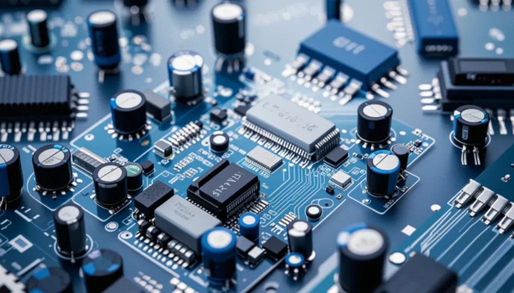
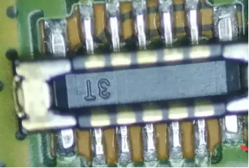
Through-hole technology (THT) is a method of assembling electronic components on a printed circuit board (PCB) by inserting component leads through drilled holes and soldering them to pads on the opposite side. Unlike surface-mount technology (SMT), which places components directly on the board’s surface, THT creates a stronger physical connection, making it ideal for high-stress or high-power applications like industrial equipment, automotive systems, and aerospace electronics.
The durability of THT connections is one of its standout features. A properly soldered through-hole joint can withstand mechanical stress, vibrations, and temperature fluctuations, ensuring long-term reliability. For instance, in automotive control units, where components are exposed to constant vibration, THT connections often outperform SMT in terms of longevity.
In the sections below, we’ll break down the through-hole assembly process and the machine techniques that ensure robust PCB connections, helping you achieve optimal results in your projects.
Understanding the Through-Hole Assembly Process
The through-hole assembly process involves several key steps to ensure components are securely mounted and soldered to the PCB. While some steps can be performed manually, machine assembly techniques are often used for efficiency and precision in larger production runs. Here’s a detailed look at the process:
- Drilling Holes: The PCB is drilled with holes at precise locations based on the circuit design. These holes are slightly larger than the component leads to allow easy insertion. For example, a typical hole diameter for a standard resistor lead might be 0.8mm to 1.0mm.
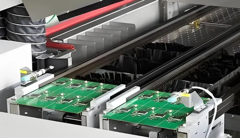
- Component Lead Insertion: Component leads are inserted into the drilled holes, either manually or using automated insertion machines. Automated machines can place components at a rate of thousands per hour, ensuring consistency in high-volume production.
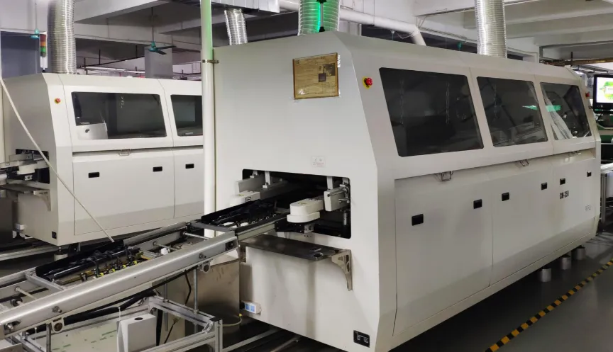
- Soldering: Once components are in place, soldering secures the leads to the PCB pads. This can be done using wave soldering for large batches or hand soldering for smaller runs or repairs.
- Inspection and Testing: After soldering, the board undergoes visual inspection and electrical testing to ensure all connections are secure and functional. Automated optical inspection (AOI) systems can detect soldering defects at a rate of over 90% accuracy.
Machine assembly plays a critical role in scaling up the through-hole assembly process, reducing human error, and ensuring consistent quality. Let’s explore some of the machine techniques used in this process.
Machine Assembly Techniques for Through-Hole Technology
Machine assembly techniques are essential for achieving efficiency and precision in through-hole technology. Below are some of the most common methods used in the industry to create durable PCB connections:
1. Automated Component Lead Insertion
Automated insertion machines are designed to place through-hole components quickly and accurately. These machines use robotic arms or pneumatic systems to insert leads into pre-drilled holes at speeds of up to 20,000 components per hour. The precision of these machines minimizes the risk of bent leads or misaligned components, which can compromise PCB durability.
For example, in high-power applications where large capacitors or connectors are used, automated insertion ensures that leads are fully seated in the holes, creating a strong mechanical bond before soldering. This step is critical for components that will experience mechanical stress during operation.
2. Wave Soldering Optimization
Wave soldering is a widely used machine technique for soldering through-hole components in bulk. In this process, the PCB passes over a wave of molten solder, which adheres to the exposed leads and pads, forming strong electrical and mechanical connections. Optimizing wave soldering parameters is key to achieving reliable results. Here are some tips for wave soldering optimization:
- Solder Temperature: Maintain the solder bath at a temperature of around 250-260°C for lead-based solder or 260-270°C for lead-free solder to ensure proper wetting without damaging components.
- Conveyor Speed: Adjust the conveyor speed to allow sufficient contact time with the solder wave—typically 2-4 seconds—depending on board thickness and component density.
- Flux Application: Use the right amount of flux to clean the leads and pads, preventing oxidation and ensuring strong solder joints. Over-application can lead to residue buildup, while under-application may cause poor wetting.
Optimized wave soldering can reduce defects like cold joints or bridging by over 80%, significantly improving PCB durability in demanding environments.
3. Selective Soldering for Precision
For PCBs with a mix of through-hole and surface-mount components, selective soldering machines offer a targeted approach. These machines use a small fountain of solder to apply molten material only to specific through-hole leads, avoiding damage to nearby SMT components. Selective soldering is ideal for complex boards where precision is critical, ensuring durable connections without overheating sensitive areas.
THT Soldering Techniques for Strong Connections
Soldering is the heart of through-hole technology, directly impacting the strength and reliability of PCB connections. While wave soldering is the go-to method for machine assembly, other THT soldering techniques are worth exploring, especially for smaller runs or rework.
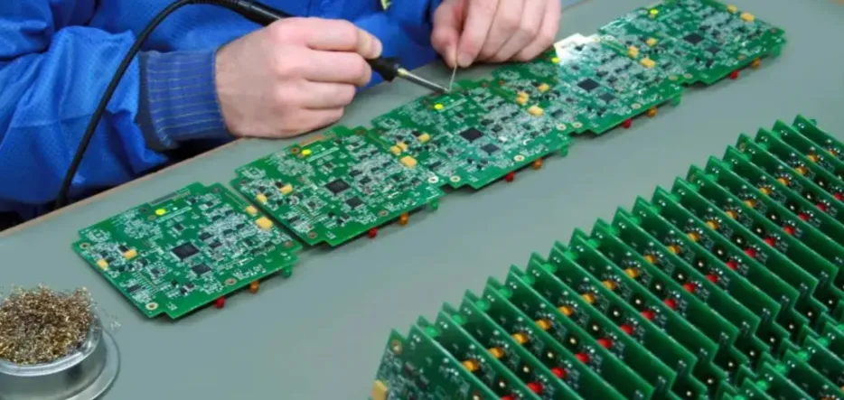
1. Hand Soldering for Manual Through-Hole Assembly
Manual through-hole assembly often involves hand soldering, where a technician uses a soldering iron to apply solder to each joint. While slower than machine methods, hand soldering allows for greater control, making it ideal for prototypes or repairs. Here are some best practices for hand soldering:
- Use a soldering iron with a temperature of 300-350°C for lead-free solder to ensure proper flow without burning the board.
- Apply solder to the joint for no more than 2-3 seconds to avoid heat damage to components.
- Ensure the joint forms a shiny, concave fillet, indicating good wetting and a strong bond.
Hand soldering, when done correctly, can achieve joint strength comparable to machine soldering, with failure rates as low as 0.1% in controlled environments.
2. Reflow Soldering for Mixed Assemblies
In some cases, through-hole components are soldered using reflow ovens, especially on boards with both THT and SMT parts. This technique involves applying solder paste to the through-hole pads, inserting the components, and then heating the board in a reflow oven. While not as common as wave soldering, reflow soldering can be effective for specific designs, achieving uniform heating and strong joints.
Enhancing PCB Durability with Through-Hole Technology
PCB durability is a critical factor in applications where boards are exposed to harsh conditions like extreme temperatures, humidity, or mechanical stress. Through-hole technology inherently offers advantages in durability due to the physical connection between component leads and the board. Here are some strategies to maximize durability during assembly:
- Plated-Through Holes (PTH): Use plated-through holes to create a conductive path through the board layers, enhancing electrical reliability and mechanical strength. PTH can reduce connection failures by up to 50% compared to non-plated holes.
- Proper Lead Length: Trim component leads to an optimal length (typically 1-2mm above the board) after soldering to prevent stress points that could lead to cracks or breaks.
- Thermal Management: Ensure adequate spacing between high-power components to prevent heat buildup, which can weaken solder joints over time. For example, maintaining a 5mm gap between power resistors can reduce thermal stress by 30%.
- Conformal Coating: Apply a protective coating after assembly to shield the board from moisture and dust, extending the lifespan of through-hole connections in harsh environments.
By focusing on these factors, you can significantly enhance the durability of your PCB, ensuring it performs reliably even under challenging conditions.
Manual Through-Hole Assembly vs. Machine Assembly: Which Is Better?
Choosing between manual through-hole assembly and machine assembly depends on your project’s scale, budget, and requirements. Manual assembly offers flexibility and is cost-effective for small batches or prototypes, allowing for quick adjustments during the process. However, it is time-consuming and prone to human error, with defect rates as high as 1-2% in non-controlled settings.
Machine assembly, on the other hand, excels in consistency and speed, making it ideal for large-scale production. Automated systems can reduce defect rates to below 0.5%, ensuring uniform quality across thousands of boards. The initial investment in machinery may be high, but the long-term savings in labor and rework costs often justify the expense.
For most professional applications requiring durable PCB connections, a combination of both methods—using machines for bulk assembly and manual techniques for fine-tuning or rework—provides the best results.
Common Challenges in Through-Hole Assembly and How to Overcome Them
Even with advanced machine techniques, through-hole assembly can present challenges. Here are some common issues and solutions:
- Cold Solder Joints: These occur when solder doesn’t properly bond with the lead or pad, often due to insufficient heat. Ensure proper soldering temperatures (around 260°C for wave soldering) and adequate flux application to prevent this issue.
- Component Misalignment: Misaligned components can result from improper insertion. Use automated insertion machines or jigs during manual assembly to maintain accuracy.
- Solder Bridging: Excess solder can create unintended connections between pads. Optimize wave soldering parameters and use solder masks to minimize bridging risks.
Addressing these challenges during the assembly process can prevent costly rework and ensure the reliability of your PCB connections.
Conclusion: Building Durable PCB Connections with Through-Hole Technology
Through-hole technology remains a cornerstone of PCB assembly for applications where durability and reliability are non-negotiable. By leveraging machine assembly techniques like automated component lead insertion and wave soldering optimization, along with effective THT soldering techniques, you can create strong, long-lasting connections that withstand the toughest conditions. Whether you opt for manual through-hole assembly for small projects or invest in automated systems for large-scale production, understanding the nuances of the through-hole assembly process is key to success.
At ALLPCB, we’re committed to helping you achieve the highest quality in your PCB projects. By applying the strategies and insights shared in this guide, you can enhance PCB durability and ensure your electronic designs perform reliably for years to come. Focus on precision in component lead insertion, optimize your soldering processes, and prioritize durability at every step to build PCBs that stand the test of time.


