 ALLPCB


Introduction
The moment of initial movement or the final centimeter during parking is often determined by a small sensor. In passenger electric vehicle traction systems, whether the motor "sees" rotor position directly affects start-up smoothness, parking experience, NVH, and vehicle functional safety. For passenger car experience and functional safety, a hybrid approach of "sensed primary control with sensorless backup" is recommended. Modern electric vehicles are becoming more perceptive of their surroundings, but precise execution still depends on the traction motor drive and sensors that improve signal quality.
Key Concepts at a Glance
Sensed FOC: The controller reads the rotor angle directly (resolver, absolute/incremental encoder, or inductive sensor) and performs field-oriented control (FOC) in the d-q reference frame.
Sensorless FOC: The controller estimates angle from terminal voltages/currents and an observer (EKF, MRAS, sliding mode, etc.), eliminating the external angle sensor.
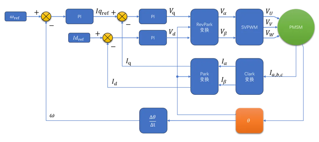
Typical FOC speed-closed-loop block diagram. In motor FOC control, whether sensed or sensorless, the rotor electrical angle is always the key input to the control system and the main target of the output.
Why "Seeing" Matters for Product Experience and Safety
Zero-speed/very-low-speed (intelligent parking, slow repositioning, hill starts): Only sensed solutions can output the required torque immediately, smoothly, and controllably at 0 RPM, avoiding surges and oscillation.
NVH (noise/vibration/harshness): Sensorless approaches at low speed often require high-frequency injection or open-loop start to establish angle, which can cause high-frequency noise and torque ripple, degrading quietness.
Functional safety (ISO 26262/ASIL): A physical sensor provides observable closed-loop feedback, which simplifies fault detection, redundancy design, and safety justification. Pure sensorless solutions incur higher validation cost and more complex risk boundaries.
Sensed (Sensor-Based) FOC: Advantages and Engineering Considerations
Advantages for passenger vehicles:
- Controllable torque at zero speed, resulting in superior start and parking feel.
- Fast dynamic response and high control accuracy, aiding efficiency optimization and precise regenerative braking.
- Supports clear fault detection and redundancy strategies, facilitating automotive safety compliance.
Engineering considerations:
- Sensors are a single-point failure source; implement parallel sensorless estimation or dual-channel hardware redundancy for fault tolerance.
- Selection must consider operating temperature, vibration resistance, EMC, interface protocol (analog, differential, SSI, BiSS, etc.), and production calibration procedures.
- Although hardware and harness costs increase, the benefits to passenger experience and safety often justify the investment.
Sensorless FOC: Value, Limitations, and Practical Role
Value:
- Reduces hardware cost and assembly complexity; at medium and high speeds (where back-EMF is significant) it can deliver good control performance.
Limitations:
- Blind starts at zero speed require open-loop or HF injection, affecting NVH.
- Sensitive to motor parameter drift (temperature rise, magnetic saturation); requires online identification and compensation.
Practical role:
- In vehicle systems, sensorless methods often serve as parallel estimators or redundancy backups, or as degraded "limp-home" modes for constrained scenarios, rather than as the sole primary control method for high-end passenger cars.
Sensor Selection Checklist (Engineering)
Key parameters to prioritize:
- Resolution and accuracy (affects zero-speed torque stability and smallest angular step)
- Vibration and shock resistance and operating temperature (automotive recommendation -40°C to +125/150°C)
- EMC immunity and resistance to stray magnetic fields
- Output interface (analog sine/cosine, differential, SPI/SSI/BiSS, etc.) and integration method for the resolver
- IP rating and sealing; harness and connector quality are equally important
- Response latency (propagation delay), which impacts phase margin for high-bandwidth control
Product Example: Inductive Motor Rotor Position Sensor (PSCI)
Example device: Amphenol Sensors (Piher) PSCI inductive motor rotor position sensor, suitable for automotive-grade traction applications.
Application scenario: Intended where automotive-level temperature tolerance, vibration resistance, and immunity to stray magnetic fields are required for fixed-axis end position feedback, especially when low-speed NVH and high reliability are priorities.
Basic principle:
An inductive motor position sensor is based on electromagnetic induction and eddy current principles. The sensor uses a set of coils printed on a PCB to detect the position of a metal target moving above them and provides demodulated sine and cosine outputs. Because this sensor does not rely on magnetic elements, it is not affected by stray magnetic fields. The basic signal-generation steps are:
- Generate alternating magnetic field: an internal oscillator drives the transmit coil to create a high-frequency alternating magnetic field.
- Induce eddy currents: when the alternating field approaches a metal target (aluminum, steel), eddy currents are induced on the target surface according to Faraday's law.
- Eddy currents create a secondary field: these eddy currents generate a secondary magnetic field opposing the original field, per Lenz's law.
- Affect receive coils: the secondary field attenuates or alters the original field, changing the voltages induced in the two receive coils. The closer the metal target to a given receive coil, the stronger the attenuation effect on that coil.
- Position calculation: by measuring and comparing the amplitude, phase, or ratio changes between the two receive coil voltages, internal circuitry can precisely compute the absolute position of the metal target relative to the coils.
Thus, the sensor uses eddy current effects to detect a metal target moving above a stationary coil set on a PCB, typically with one transmit coil and two receive coils arranged at a defined angle. The receive coils provide two signals corresponding to sine and cosine.
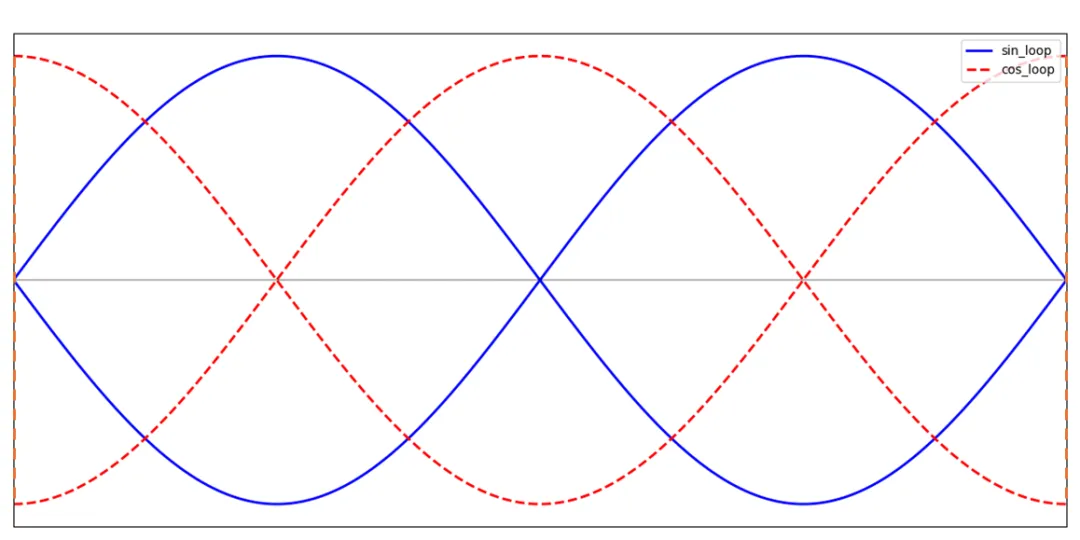
After amplification and calibration, the receive coil signals produce sine and cosine outputs representing shaft angle. Outputs can be single-ended or differential for improved interference resistance. After ADC conversion, the measured SIN and COS values give the current electrical angle:
θ_el_sensor = atan2(SIN, COS)
With a simple conversion, one can obtain the motor electrical angle and the mechanical angle; in practice, look-up tables are often used for efficiency.
Key specification highlights (excerpt):
- Accuracy ±1° (electrical), effectively infinite resolution with analog sine/cosine output
- Output: single-ended (1–4 V) or differential (-3 V to +3 V) demodulated sine/cosine, suitable for controller front-ends
- Immune to stray magnetic fields; can be mounted close to the motor shaft
- Environment and mechanics: IP67 / IP69K sealed, operating temperature -40°C to +150°C, shock and vibration resistant
- Electrical: 5 V ±10% supply, max 15 mA, propagation delay 4.2 μs, electrical speed rating up to 600,000 rpm (limit margin)
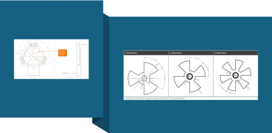
- Typical variants: PSCI-3PP-05 (3 pole pairs), PSCI-4PP-05 (4 pole pairs), PSCI-6PP-05 (6 pole pairs)
Rationale: Compared with resolvers, the PSCI approach can be more compact and cost-competitive while offering resolver-grade durability. For applications that require both low-speed NVH performance and robustness in high-temperature, high-vibration environments, this class of inductive sensors is a strong candidate for the sensed primary control path.
System-Level Architecture Recommendations
Recommended architecture: sensed primary control + parallel sensorless estimation (online cross-check) + clearly defined degradation strategy.
Primary (sensed): automotive-grade position sensor (PSCI, resolver, or high-reliability absolute encoder).
Backup (sensorless): run an observer in parallel to perform plausibility checks; on sensor failure switch to a limited mode (speed/torque limits) and instruct the vehicle to return for service.
Switching strategy: predefine fault detection thresholds, switch conditions, post-switch constraints (max torque/speed/alarms), and user notification logic.
Online parameter identification: implement online or periodic identification of motor parameters to improve the robustness of sensorless estimation (temperature compensation, magnetic saturation models).
Verification, Calibration, and Production Considerations
Verification scope: test across temperature, humidity, EMC, aging, mechanical loosening, harness disconnection, ADC/front-end fault injection, and other operating conditions.
Production calibration: automate zero/bias/gain calibration flows to ensure production consistency.
Functional safety: perform FMEA/FMEDA per ISO 26262, prepare degradation scenarios and switching test records to demonstrate safe controllability under single-point faults.
ADC sampling: use dual ADC channels triggered simultaneously to reduce angle calculation error at high speeds.
It is advisable for traction teams to engage harness and interconnect suppliers early for coordinated mechanical, electrical, and EMC design to ensure project efficiency and final quality.
Closing Remarks
From electric vehicles to humanoid robots, accurate control of permanent magnet motors is central to modern electrified systems. Sensors function as the interface between the physical world and intelligent devices; their measurement accuracy, response, and reliability define the effective operating envelope of the system.


