ALLPCB


Definitions
Ripple
Ripple is the unwanted AC component superimposed on a DC level, containing both periodic and random elements. In the context of a specified output voltage and output current, ripple refers to the AC voltage peak-to-peak present on the output. In a narrow sense, ripple voltage denotes the mains-frequency AC component contained in the output DC voltage.
Noise
Noise refers collectively to all signals other than the intended signal in an electronic circuit. Historically the term described electronic signals that produced audible disturbances in audio equipment, but the concept has since been broadened to include any undesired electronic signals that affect circuits, such as those that cause visible artifacts on a display. Any signal in a circuit other than the intended signal can be considered noise, regardless of its perceptible effect.
Ripple or oscillations in a circuit are forms of noise. A radio-frequency signal that is a desired signal for one receiver can be noise for another; thus noise is a signal while interference denotes an effect: an adverse reaction in a circuit caused by noise.
Harmonics
Harmonics are frequency components in a current or voltage that are integer multiples of the fundamental frequency. When a periodic non-sinusoidal waveform is decomposed by Fourier series, the components above the fundamental are harmonics.
Since the AC mains fundamental is a single frequency, any component not at the mains frequency can be considered a harmonic. Harmonics arise when a sinusoidal voltage is applied to a nonlinear load, causing the current waveform to distort and produce non-sinusoidal currents. Typical nonlinear loads include UPS systems, switching power supplies, rectifiers, variable-frequency drives, and inverters.
Overview of Ripple and Noise in Switching Power Supplies
Compared with linear supplies, switching power supplies (including AC/DC converters, DC/DC converters, AC/DC modules, and DC/DC modules) have higher conversion efficiency, commonly 80%-85% and in some designs up to 90%-97%. They also use high-frequency transformers instead of bulky mains-frequency transformers, which reduces weight and size and broadens their applications.
The downside is that switching devices operate in a high-frequency switching state, producing larger ripple and noise on the output. Typical ripple and noise voltages are around 1% of output voltage (lower-end units around 0.5%); the best products may still have tens of millivolts of ripple and noise. Linear supplies use a pass transistor in linear mode and exhibit negligible ripple and very low noise, often measured in microvolts.
This article summarizes the causes of ripple and noise in switching supplies, measurement methods and setups, measurement standards, and measures to reduce ripple and noise.
Causes of Ripple and Noise
The output of a switching power supply is not pure DC; it contains AC components that manifest as ripple and noise. Ripple is the periodic fluctuation of the DC output caused by the switching actions. Each on/off transition transfers energy from input to output, creating charge and discharge cycles that cause output voltage fluctuation. The ripple frequency matches the switching frequency. Ripple voltage is the peak-to-peak difference between ripple peaks and valleys and depends on the input and output capacitances and their quality.
Noise has two primary origins: noise generated internally by the switching supply and external electromagnetic interference (EMI). EMI may couple into the supply via radiation or via the power lines. Internal noise is a high-frequency pulse train produced by the narrow voltage spikes at the switching device’s turn-on and turn-off instants; this is called switching noise. The pulse-train frequency content extends well above the switching frequency, and noise voltage is usually quoted as a peak-to-peak value. Noise amplitude is strongly affected by the converter topology, parasitic elements in the circuit, and PCB layout.
An oscilloscope can show ripple and noise waveforms, as in the figure below. Ripple frequency corresponds to the switching device frequency, while the dominant noise frequency components are higher, often harmonics of the switching transitions. The sum of the peak-to-peak ripple voltage and the peak-to-peak noise voltage gives the overall ripple-and-noise figure, typically expressed in mV peak-to-peak.
Measurement Methods
Ripple-and-noise voltage is a key performance parameter for switching supplies, so accurate measurement is important. The current standard approach is to use a wide-bandwidth oscilloscope, which can accurately capture ripple and noise values.
Switching supplies vary widely by topology, switching frequency, output power, and technical requirements. Manufacturers typically use oscilloscope-based methods, but measurement fixtures and exact procedures differ, so each manufacturer may have its own internal standard. Consistent measurement fixtures are required for comparable results.
The block diagram of a typical oscilloscope-based measurement setup consists of the unit under test, a load, the oscilloscope, and measurement leads. Some setups include inductors, capacitors, or resistors in the measurement path.
Although this looks similar to other waveform measurement circuits, the requirements are stricter. Key requirements for measuring ripple and noise are:
- Prevent environmental electromagnetic fields (EMI) from coupling into the output so that the measured noise is not contaminated by external EMI.
- Prevent EMI generated by the load circuit from affecting the measurement.
- For small switching modules that lack adequate output capacitance, add appropriate output capacitance during measurement.
To meet the first requirement, keep measurement leads as short as possible and use twisted pair (to cancel common-mode noise) or coaxial cable. General-purpose oscilloscope probes are not suitable; use specialized probes. The measurement point should be at the power-supply output; measuring at the load can introduce significant error. To meet the second requirement, use a resistive dummy load.
It is common for users to measure ripple and noise and get values much worse than the product specification. This usually stems from inappropriate measurement fixtures, incorrect choice of measurement point, or use of a general-purpose probe that picks up extraneous EMI.
Twisted-Pair Measurement Setup
The twisted-pair setup uses a 300 mm (12 inch) twisted pair of #16 AWG wire connected to the +OUT and -OUT of the unit under test, with a resistive dummy load between +OUT and -OUT. At the twisted-pair end, connect a 4TμF electrolytic capacitor (tantalum) and feed the signal into an oscilloscope with 50 MHz bandwidth (some manufacturer standards use 20 MHz). When connecting the measurement point, place one end on +OUT and the other on the ground plane.
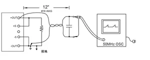
Note that the ground lead at the end of the twisted pair should be kept as short as possible and clamped within the probe ground ring.
Parallel-Line Measurement Setup
The parallel-line setup uses two parallel copper strips with capacitors connected at the output. In the figure, C1 is a multilayer ceramic capacitor (MLCC) of 1 μF and C2 is a 10 μF tantalum electrolytic capacitor. The combined voltage drop across the two parallel copper strips should be less than 2% of the output voltage. This method better approximates real operating conditions but is more susceptible to picking up EMI.
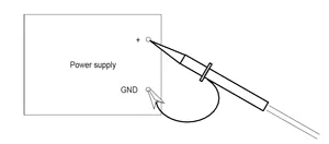
Dedicated Oscilloscope Probe
A dedicated oscilloscope probe can be connected directly to the power output. The probe typically includes a ground ring; the probe tip contacts the power output positive terminal and the ground ring contacts the negative terminal (ground). Ensure reliable contact.
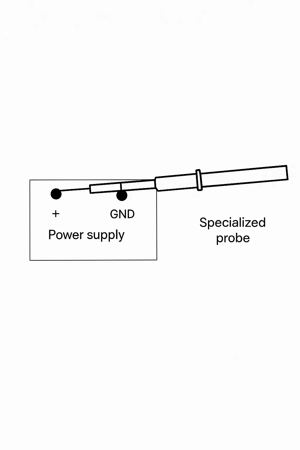
Do not use general-purpose oscilloscope probes because their ground leads are unshielded and long, making them prone to picking up external electromagnetic fields and producing large apparent noise. The larger the loop area formed by the probe ground, the greater the susceptibility to interference.
Coaxial Cable Measurement Setups
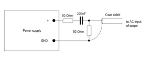
Two coaxial cable setups are commonly used. In one, an R-C network at the unit output is fed into a 50 Ω coaxial cable and then into the oscilloscope AC input. In another, the coaxial cable is connected directly to the power output, and at both ends of the coax are series components such as a 0.68 μF ceramic capacitor and a 47 Ω/1 W carbon film resistor before connecting to the oscilloscope.
Measurement Standards
Different measurement fixtures yield different results for the same unit under test. Using a common standard measurement fixture is necessary for comparable results.
A standard specifies that two capacitors C2 and C3 be connected in parallel within 150 mm of the unit output positive and negative terminals. C2 is a 22 μF electrolytic capacitor and C3 is a 0.47 μF film capacitor. At the common connection of these two capacitors, connect the load and a 50 Ω coaxial cable no longer than 1.5 m. The other end of the coaxial cable connects to a 50 Ω resistor R in series with a 4700 pF capacitor C1, which then connects to the oscilloscope. The oscilloscope bandwidth should be 100 MHz. Keep the connections at both ends of the coax as short as possible to avoid picking up radiated noise.
Testing should be performed under stable ambient conditions, with the unit under test supplied at nominal input voltage and operating at rated output voltage and load current.
Measures to Reduce Ripple and Noise
Beyond switching noise, in AC/DC converters the mains input is often full-wave rectified and filtered by capacitors, producing a pulsed current waveform that contains high-order harmonics and increases output noise. Good designs include a power factor correction (PFC) stage to make the input current closer to sinusoidal, reduce higher harmonics, improve power factor to around 0.95, and reduce distortion on the mains.
The magnitude of output ripple and noise depends on converter topology, circuit design details, and PCB layout. Techniques such as multiphase outputs can effectively reduce ripple. Switching frequencies have increased over time: lower-end designs operate at tens of kilohertz, typical designs at several hundred kilohertz, and some designs exceed 1 MHz. Because ripple and noise frequencies are high, the simplest way to reduce them is to add a passive low-pass filter in the power path.
EMI Reduction
To reduce susceptibility to external electromagnetic radiation, use a metal enclosure for shielding. To reduce conducted EMI entering from the mains, add an EMI filter at the supply input.