ALLPCB


Overview
Microcontroller pins typically include a driver circuit that can be configured for different digital and analog interfaces. Common output modes are push-pull and open-drain.
Push-Pull Output
Push-pull output uses a pair of transistors to actively drive the pin both high and low. In integrated circuits this is usually implemented with complementary MOSFETs (P-MOS and N-MOS).
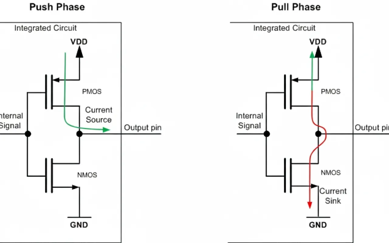
Operation summary:
- Drive high: the P-MOS conducts, sourcing current from VDD to the output while the N-MOS is off.
- Drive low: the N-MOS conducts, sinking current from the output to GND while the P-MOS is off.
Push-pull drivers should not be tied together on a shared bus. If one device drives high while another drives low, a direct current path from VCC to GND will form through the conducting transistors, potentially causing a short circuit and damaging the ports. For this reason push-pull outputs are typically used for point-to-point or unidirectional interfaces (for example SPI, UART).
Because push-pull drivers can actively source and sink current, they provide stronger drive and produce faster edge rates for digital signals. A push-pull output can usually be configured as an input by turning off both transistors, placing the pin in a high-impedance state.
Related Reading: What Is GPIO? Architecture and Working Principle
Open-Drain Output
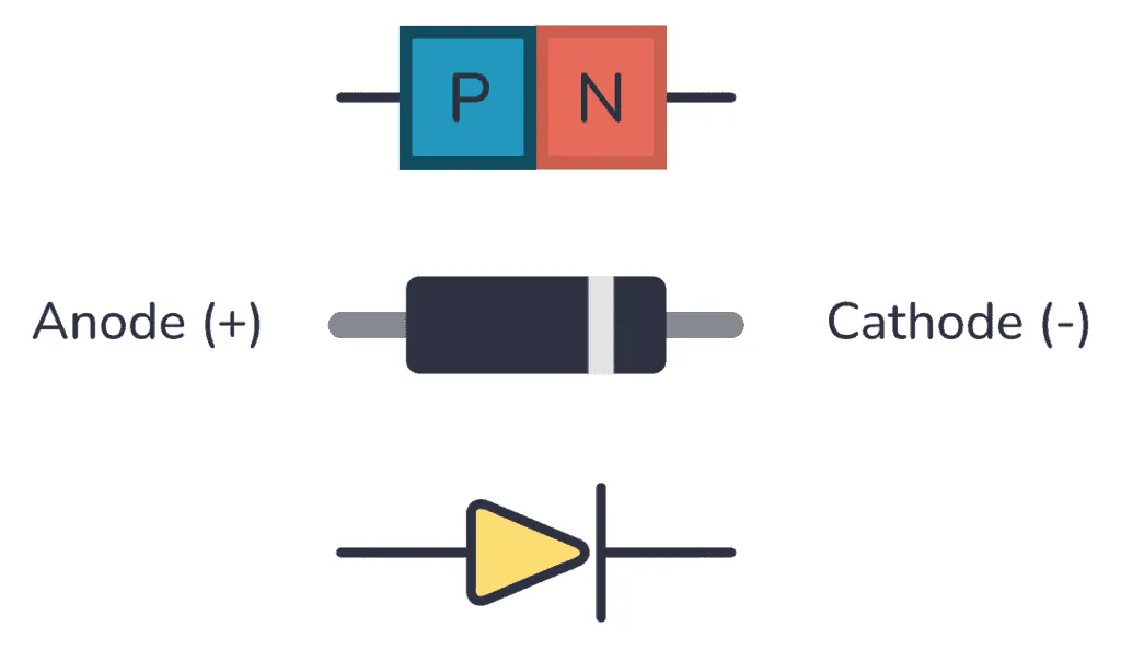
Open-drain (OD) output, historically known as open-collector for bipolar implementations, provides an active low and a high-impedance state. A pull-up resistor is required to obtain a valid high level.
In its simplest form, an open-drain output uses a single N-MOS that pulls the line to ground when active; when inactive the output is left floating. Because the high level is provided by an external pull-up, the driver itself cannot source current to drive the line high.
Open-drain outputs are commonly used on shared bidirectional lines where multiple devices may pull the line low (for example I2C, One-Wire). The line is held high by the pull-up resistor and any device can assert a low by pulling the line down.
Selection of the pull-up resistor requires balancing trade-offs:
- Edge rate: the pull-up and the line capacitance form an RC low-pass filter. A lower resistance yields faster rise times and better signal performance.
- Power: a lower pull-up resistance increases static current when the line is pulled low, increasing power consumption.
- Noise immunity: a higher pull-up resistance weakens the pull-up and makes the line more susceptible to external interference.
Comparison
- Push-pull is typically used for unidirectional signals; open-drain is often used for shared bidirectional buses.
- Open-drain solutions include a pull-up so they can exhibit higher static power consumption in some states.
- Push-pull drivers generally switch faster than open-drain configurations with the same pull-up.
References
- Open Drain Output vs. Push-Pull Output
- What is GPIO push-pull and open-drain output
This article is licensed under CC BY-NC-SA 4.0. Please indicate the source when reprinting.