 ALLPCB


Overview
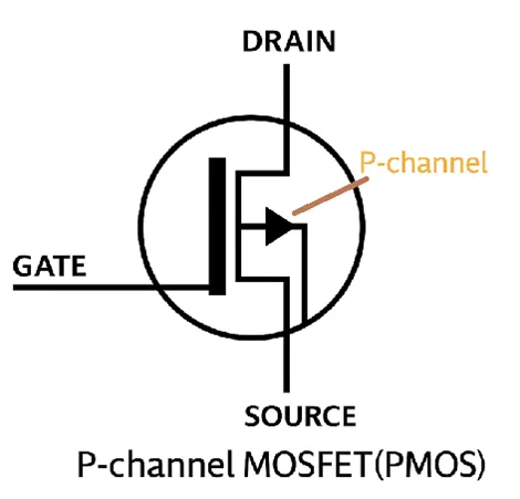
Traditional reverse-protection circuits typically use a PMOS transistor. The PMOS gate is tied to ground through a resistor. When the input is connected with the correct polarity, current initially flows through the PMOS body diode to the load. Once the forward voltage exceeds the PMOS threshold, the main channel conducts, Vds drops, and current transfers to the main channel, achieving lower loss and reduced temperature rise.
Operation Details
In this topology, when the voltage across the MOSFET (initially the body-diode drop) exceeds the gate-source threshold, the MOSFET turns on. The body diode is effectively bypassed and its voltage drop no longer determines the forward voltage.
R1 is the LED series current-limiting resistor; when it conducts the LED lights to indicate the power is present.
When the supply is connected in reverse, the PMOS gate-source voltage becomes positive and the MOSFET remains off, preventing conduction.
Rg is used to reduce pulse current and the effects of voltage division when conduction events occur.
If the gate-source voltage becomes excessive, the zener diode D will enter reverse breakdown. Within a specified reverse current range, the reverse voltage remains approximately constant. The zener therefore limits VGS during input overvoltage conditions, protecting the MOSFET from gate overvoltage.
Body Diode Orientation
Pay attention to the orientation of the MOSFET body diode. If the body diode is oriented toward Vin, then on reverse connection current can flow from GND through the body diode to Vin, creating a direct short and negating the reverse-protection function.
Limitations of PMOS Reverse Protection
Using a PMOS for reverse protection has three main drawbacks.
- Higher standby current: The VGS drive and protection network incur quiescent current losses, typically from the zener diode and its series resistor. That resistor value affects standby power. Increasing the resistor to reduce standby current can prevent the zener from conducting reliably, risk VGS overvoltage, and degrade PMOS switching speed.
- Backfeed current: During input drop tests, a PMOS can remain conducting as the input falls. The charge on downstream capacitors can then backfeed and effectively reverse the supply polarity, causing system power faults or interruptions.
- Cost: PMOS devices are generally more expensive, so PMOS-based reverse protection is typically used for higher-current scenarios, commonly above about 3 A.


