Overview
In circuit design, MOSFETs and IGBTs frequently appear as power switching devices. They can look similar and share many specifications, yet designers choose one or the other depending on application requirements for voltage, current, and switching frequency. This article explains the differences and typical use cases for MOSFETs and IGBTs.
What is a MOSFET?
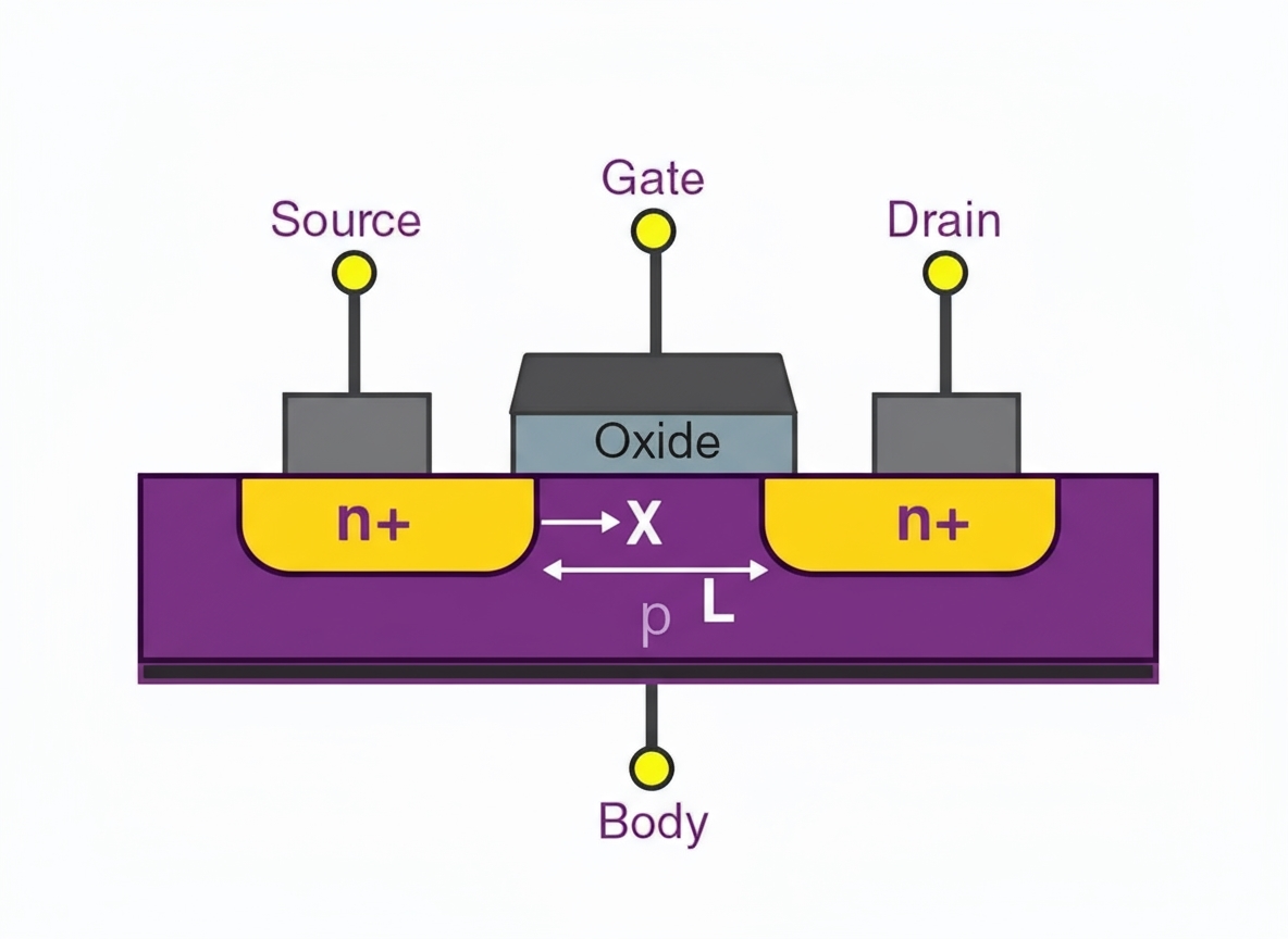
Field-effect transistors include junction FETs (JFETs) and insulated-gate FETs (MOSFETs). MOSFET stands for metal-oxide-semiconductor field-effect transistor. Because the gate is isolated by an insulating layer, it is called an insulated-gate FET. MOSFETs are available as N-channel or P-channel, and in depletion and enhancement modes.
Some MOSFETs include an internal diode known as the body diode, parasitic diode, or free-wheeling diode.
There are two common explanations for the role of the body diode:
- It can provide a current path that helps prevent MOSFET damage under certain overvoltage conditions by conducting before the MOSFET structure is destroyed.
- It protects the MOSFET against damage when source and drain are reversed or when the circuit experiences reverse induced voltages, by providing a path for that reverse voltage.
MOSFETs are characterized by high input impedance, fast switching, good thermal stability, and voltage-controlled operation. They are commonly used as amplifiers and electronic switches.
What is an IGBT?
IGBT stands for insulated-gate bipolar transistor. It is a composite semiconductor device that combines features of a MOSFET and a bipolar junction transistor. IGBTs offer high input impedance, low control power consumption, simple control circuitry, high-voltage capability, and high current handling, which makes them widely used in power electronics.
Symbols for IGBTs are not fully standardized, and schematic symbols may borrow elements from BJT and MOSFET symbols. Presence of a body diode should not be inferred solely from the schematic symbol, unless the device documentation explicitly states otherwise.
The internal diode in many IGBTs is intentionally provided to protect the device's relatively weak reverse voltage capability; this diode is commonly called a free-wheeling diode (FWD). To check whether an IGBT includes an internal diode, measure resistance between the collector and emitter with a multimeter. If the device is good and the resistance reads open circuit, that indicates no internal diode is present.
IGBTs are well suited to applications such as motors, inverters, switch-mode power supplies, lighting circuits, and traction drives.
Structural Characteristics
Structurally, an IGBT can be seen as a MOSFET with an additional layer on the drain that creates the bipolar behavior. The effective equivalent circuit of an IGBT is a combination of a MOSFET and a bipolar transistor. While MOSFETs can have relatively high on-resistance, IGBTs address this by providing lower on-resistance at high voltages.
For similar power ratings, IGBTs are often slower than MOSFETs because they exhibit a turn-off tail current. The longer turn-off tail requires longer dead time in drive circuits, which limits the achievable switching frequency.
Choosing Between MOSFET and IGBT
Selection depends on system voltage, current, switching power, and frequency requirements:
- MOSFET advantages: better high-frequency performance; operating frequencies can reach hundreds of kHz and into the MHz range. Drawback: higher on-resistance, which leads to greater conduction losses in high-voltage, high-current applications.
- IGBT advantages: superior for low-frequency, high-power applications due to lower conduction loss and higher voltage tolerance. Drawback: slower switching because of turn-off tail effects.
Typical MOSFET applications include switch-mode power supplies, ballasts, high-frequency induction heating, high-frequency inverter welders, and communication power supplies. Typical IGBT applications include welding machines, inverters, variable-frequency drives, electroplating power supplies, and high-power induction heating.
 ALLPCB


