ALLPCB


A microcontroller's (MCU) clock circuit is a critical component of the system, providing the fundamental clock signal that drives its internal timing and operations.
The clock signal is crucial for an MCU as it determines its overall performance and operational stability. It is used for timing control and data synchronization, coordinating the various operations within the microprocessor to occur at the correct moments.
In an MCU, the clock signal is typically generated by a clock generator circuit, which can be a crystal oscillator, a ceramic oscillator, or another type of clock source. These sources oscillate at a specific frequency to produce a stable clock signal, which is then fed to the MCU's clock input pin.
MCU clock circuits can be categorized into two types:
- Internal Clock: Some MCUs feature an internal clock generator that produces the clock signal on-chip. This is typically generated by an internal oscillator circuit, and its frequency can be adjusted by setting registers or control bits.
- External Clock: Other MCUs require an external clock source, such as a crystal. The external source is provided by an external circuit (like a crystal oscillator) and is connected to the MCU's clock input pins.
Clock circuits can also include additional features like frequency dividers and phase-locked loops (PLLs). A divider can reduce the clock signal to a lower frequency for use by different modules, while a PLL can multiply or divide the input clock signal to generate various clock frequencies.
An MCU clock circuit generates a stable clock signal, which is fundamental for the MCU's normal operation and determines its speed and performance. The specific design and configuration depend on the MCU model and application requirements.
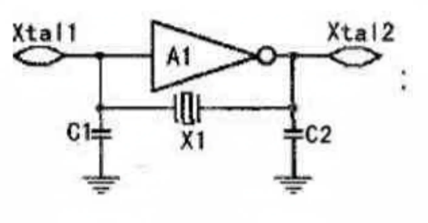
The clock circuit is essentially an oscillator that provides a "heartbeat" for the MCU. All MCU operations must be performed under the control of this beat; without a clock circuit, an MCU cannot function correctly. The clock circuit itself does not control operations directly; instead, firmware instructs the MCU to perform tasks in sync with the clock. For example, the MCS-51 microcontroller contains a high-gain inverting amplifier on-chip. The input to this amplifier is the XTAL1 pin, and the output is the XTAL2 pin. This amplifier, along with external components, forms the oscillator circuit. Depending on the hardware configuration, the MCU's clock can be configured in either an internal or external mode.
The diagram shows a self-excited oscillator circuit. In the internal clock mode, a quartz crystal and two small capacitors (C1 and C2) must be connected across the XTAL1 and XTAL2 pins to form the oscillator. Typically, C1 and C2 are around 30 pF, and the crystal frequency is between 1.2 MHz and 12 MHz. For an external clock configuration, the XTAL1 pin should be grounded, and the external clock signal should be connected to the XTAL2 pin. The external signal does not have strict requirements, as long as it has a sufficient pulse width and its frequency is below 12 MHz. The signal from the crystal oscillator is fed into the internal clock circuitry from the XTAL2 pin. This signal is divided by two to generate a two-phase clock (P1 and P2) for the MCU's use. The period of this internal clock signal is called a state time (S), which is twice the oscillator's period. The P1 signal is active during the first half of each state, and the P2 signal is active during the second half. The CPU uses these P1 and P2 phases as the basic rhythm to coordinate the operations of all its parts.
Related Reading: Clocking Techniques for CCD Readout
Key Functions of an MCU Clock Circuit
An MCU's clock circuit plays a vital role in the system and serves several key purposes:
- Timing Control: The clock circuit provides a precise clock signal, allowing the timing controller to synchronize various operations. This enables instructions to be executed at specific intervals, achieving accurate time control and timing operations.
- Data Sampling and Synchronization: The clock signal enables the MCU to accurately sample and synchronize external input/output data. It ensures that data is reliably read and transmitted at the correct time.
- Coordination of On-Chip Modules: Different functional modules within an MCU (such as the CPU, memory, and peripherals) often operate at different speeds. The clock circuit can provide a unified clock signal to these modules, enabling them to work in a coordinated, synchronized, and consistent manner.
- System Stability and Reliability: The stability of the clock signal is crucial for the overall stability and reliability of the MCU system. A stable clock signal ensures the MCU operates correctly and performs consistently as expected.
- Power Consumption Reduction: By controlling the clock frequency and enabling or disabling clocks for specific modules (clock gating), the clock circuit helps reduce the MCU's power consumption. This is especially important in power-constrained applications where energy efficiency and battery life are critical.
Related Reading: Clock Gating Implementation in IC Design
In summary, the MCU clock circuit is essential to the system. It provides the fundamental timing control, data sampling, and synchronization functions that enable the MCU to operate as intended and coordinate its internal modules. The stability and reliability of the clock circuit directly impact the performance and stability of the entire MCU system.