 ALLPCB


Introduction
Schottky diode, also called Schottky barrier diode (SBD), is a low-power, very fast semiconductor device often used as a high-frequency, low-voltage, high-current rectifier, freewheeling diode, or protection diode. In practice, Schottky diodes can be easily damaged; avoiding unnecessary failures during use is an important consideration in product design. This article summarizes Schottky diode characteristics and usage notes for reference.
Main Advantages and Disadvantages of Schottky Diodes
- Short reverse-recovery time. Reverse-recovery time is the time required for a diode to switch from the forward-conducting state to the non-conducting state. Because Schottky conduction involves only majority carriers and no minority carriers, it theoretically has no reverse-recovery time, making Schottky diodes among the fastest diodes.
- Low forward voltage drop. Typical forward voltage drop is very small, generally 0.2–0.45 V, much lower than that of fast-recovery diodes, so the conduction loss is relatively low.
- The main drawback is reverse leakage current. Leakage depends on reverse voltage and junction temperature, increasing with both. Leakage current increases exponentially with temperature, and its maximum value depends on the manufacturing process.
Usage Notes
- The actual operating current should be lower than the diode's rated forward current, and should not exceed about 60% of the rated current.
- The maximum operating voltage must be lower than the diode's breakdown voltage, and should not exceed about 70% of the rated voltage. However, selecting an excessively high voltage rating is not ideal because VF increases with higher voltage ratings, which raises power dissipation and cost.
- The actual temperature rise during operation should be below the diode's maximum junction temperature with margin to ensure stable operation.
- Different Schottky models specify forward voltage versus IF(AV) differently; manufacturers use different test standards and test temperatures.
Why Paralleling Schottky Diodes Is Not Recommended
From semiconductor physics, under static conditions the diode current-voltage relationship can be written as:
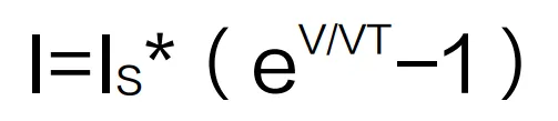
In the equation, I is the diode current and Is is the diode reverse saturation current. Is is typically on the order of 8–10 μA and increases with temperature. V is the voltage applied across the diode, and VT is the thermal voltage of the PN junction. At room temperature VT = 26 mV. Assume a typical Schottky forward drop of 0.4 V. Due to manufacturing variations and other factors, the forward voltage can differ by about 0.1%. If two parallel Schottky diodes have forward drops of 0.400 V and 0.401 V respectively, and if Is is assumed to be 2 μA, then from equation (1) we obtain:
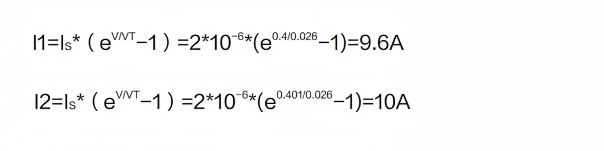
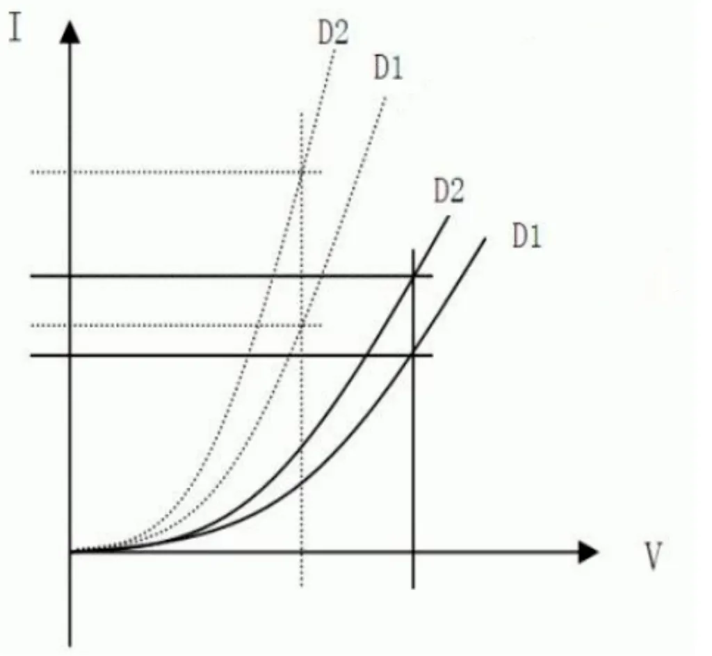
The calculation shows that paralleling Schottky diodes does not achieve equal current sharing. Considering that reverse leakage, the main drawback of Schottky diodes, increases with temperature and reverse voltage and that Is grows exponentially with temperature, the negative temperature coefficient of VF produces positive feedback. The result is one diode taking most of the load while the other is lightly loaded. If the design is inadequate, the overloaded diode may overheat and cause system failure.
Note
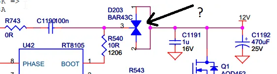
“Not recommended” here means that when a single Schottky cannot meet system requirements, you should not parallel two identical Schottky diodes of the same specification to try to meet the need. If a single diode already meets the requirement, adding another identical diode in parallel will generally improve margins. For example, with a 12 V input and 5 V/2.4 A output, one SS54 in an SMA package may not be sufficient due to small package size and high temperature during prolonged operation. Paralleling two SMA SS54 devices can lead to the issues described above. In this case, using a single SS54 in an SMC package can meet the requirement. If a single SMC SS54 already satisfies the application, paralleling another SMC SS54 would perform better than a single SMC device.


