ALLPCB


We introduced three fundamental modes of spatial EM wave propagation: ground wave, skywave, and line-of-sight (LOS). As electromagnetic wave frequencies increase, line-of-sight propagation has become the predominant mode.
But does line-of-sight mean a signal can be received as long as there is a visual path? Is the attenuation of EM waves in space significant? What factors must be considered for EM wave propagation?
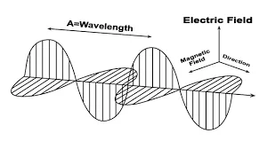
A key characteristic of electromagnetic waves is their ability to propagate without a medium. As long as electric and magnetic fields can oscillate and regenerate each other, they can travel forward at the speed of light.
This energy, which propagates without a carrier medium, can travel through free space without loss. While "lossless" might suggest it can travel forever, it does not mean its intensity remains constant. Electromagnetic wave propagation is divergent; as the distance from the source increases, the waves spread out, and their intensity gradually decreases.
Therefore, distance is a primary challenge in EM wave propagation. Even high-energy electromagnetic waves like sunlight experience this. The varying distances and angles of Earth relative to the sun result in different seasons with distinct temperature changes.
Related Reading: The Story Behind the Discovery of Electromagnetic Waves
Free Space Path Loss
Let's assume there are two antennas: a transmitting antenna with power Pt and gain Gt, and a receiving antenna with gain Gr. The distance between them is R, which is sufficiently large to be in the far-field region of both antennas. What is the power Pr received by the receiving antenna?
If we assume the transmitting antenna is an isotropic (omnidirectional and lossless) radiator, the power density at a distance R is:
Power Density = Pt / (4πR²)
Considering the gain Gt of the transmitting antenna, the power density at the receiver is:
Power Density = (Pt * Gt) / (4πR²)
If the effective area of the receiving antenna is Ae, then the power received by the antenna is:
Pr = [(Pt * Gt) / (4πR²)] * Ae
The effective area of an antenna is a physical quantity related to its operating wavelength (λ) and gain (Gr):
Ae = (Gr * λ²) / (4π)
Thus, the received power can be calculated as:
Pr = Pt * Gt * Gr * (λ / (4πR))²
This is the well-known Friis transmission equation, first derived by Harald T. Friis of Bell Labs in 1945 and detailed in a 1946 paper.
This equation is also known as the free space path loss equation. If we define propagation loss as the ratio of the receiver's input power (Pr) to the transmitter's output power (Pt), we can derive it from the formula above.
Loss = Pt / Pr = (4πR / λ)² * (1 / (Gt * Gr))
In decibel (dB) form, this is:
Loss (dB) = 20log(4πR / λ) - Gt(dB) - Gr(dB)
If we ignore the gains of the transmitting and receiving antennas, the free space path loss formula can be simplified to:
Loss = (4πR / λ)² = (4πRf / c)²
This is also known as the Friis transmission equation. If distance R is in kilometers (km) and frequency f is in megahertz (MHz), the equation can be converted to a more common form:
Loss (dB) = 32.44 + 20log(f) + 20log(R)
Note: The above is the well-known free space path loss formula.
For example:
Consider a 5G base station with a transmit power of 100W, an antenna gain of 20 dBi, and an operating frequency of 3.5 GHz. What is the power in watts received by a mobile phone 2 km away?
First, calculate the free space path loss (Lfs):
Lfs (dB) = 32.44 + 20log(3500 MHz) + 20log(2 km) = 32.44 + 70.88 + 6.02 = 109.34 dB
A typical mobile phone has an omnidirectional antenna with an internal gain of 0 to 1 dBi. Assuming a gain of 0 dBi, the received power is:
Pr (dBm) = Pt (dBm) + Gt (dBi) - Lfs (dB) + Gr (dBi)
Pt = 100W = 50 dBm
Pr (dBm) = 50 + 20 - 109.34 + 0 = -39.34 dBm
Converting back to watts, -39.34 dBm is approximately 0.0000011 W, or 1.1 microwatts.
In wireless communications, it is often said that "a 6 dB increase in power doubles the transmission distance." This 6 dB figure can be derived from the `20log(R)` term in the path loss formula. If the distance R doubles, the path loss increases by `20log(2)`, which is approximately 6 dB.
Related Reading: High-Frequency EM Waves and Their Interference
Atmospheric Attenuation
Propagation on Earth's surface is different from that in free space. In addition to intensity decay due to distance, the atmosphere also has an effect. The atmosphere and precipitation can absorb and scatter electromagnetic waves, particularly those with frequencies above 1 GHz.
ITU-R P.676-11 provides attenuation rate curves caused by atmospheric gases. These curves show that attenuation peaks at specific frequencies due to molecular resonance. The first resonance peak, caused by water vapor absorption, occurs at approximately 23 GHz. The second, from dry air (mainly oxygen) absorption, is at 62 GHz. A third peak from dry air is at 120 GHz, followed by two more water vapor absorption peaks at 180 GHz and 350 GHz.
Therefore, communication systems operating in the atmosphere should avoid these high-attenuation frequency bands.
Additionally, precipitation has a significant impact on electromagnetic waves above 10 GHz.
Real-world attenuation models are far more complex. However, the Friis transmission equation serves as a useful tool for quickly estimating the coverage range of a wireless station and assessing the impact of its radiation.