 ALLPCB


If you're dealing with issues in rigid board SMT assembly, you're not alone. Common defects like solder bridging, tombstoning, component misalignment, insufficient solder, and others can disrupt production and affect product reliability. In this practical guide, we'll walk you through identifying, troubleshooting, and preventing these SMT assembly defects using proven techniques and tools like AOI inspection in SMT. Whether you're an engineer or a production manager, you'll find actionable solutions to improve your assembly process and ensure high-quality results.
Let's dive into the details of these common issues, their causes, and how to fix them step by step.
What is SMT Assembly and Why Do Defects Matter?
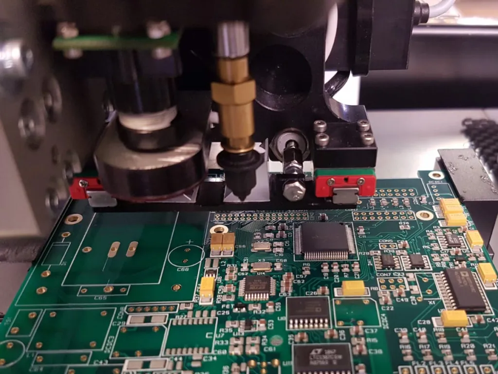
Surface Mount Technology (SMT) is a method used to mount electronic components directly onto the surface of a printed circuit board (PCB). This technique is widely used in rigid board assembly for its efficiency, compact design capabilities, and suitability for high-volume production. However, even small errors in the SMT process can lead to defects that compromise functionality, increase rework costs, and delay production timelines.
Defects in SMT assembly can result in anything from minor performance issues to complete product failures. With the increasing demand for smaller, more complex devices, ensuring defect-free assembly is more critical than ever. By understanding and addressing common SMT assembly defects, manufacturers can save time, reduce waste, and deliver reliable products to their customers.
Common SMT Assembly Defects: Identification and Causes
Before diving into troubleshooting, let's identify the most common SMT assembly defects encountered in rigid board production. Understanding the root causes of these issues is the first step toward prevention.
1. Solder Bridging
Solder bridging occurs when excess solder creates an unintended connection between two or more pads or leads, causing a short circuit. This defect is often visible as a small blob of solder spanning adjacent connections.
Causes:
- Excessive solder paste applied during the stencil printing process.
- Incorrect stencil design or misalignment during printing.
- Insufficient spacing between pads, especially in high-density designs.
- Improper reflow soldering temperature profiles leading to solder flow issues.
Impact: Solder bridging can cause electrical shorts, leading to circuit malfunction or complete failure. In high-density boards, this defect can be particularly challenging to detect without proper inspection tools.
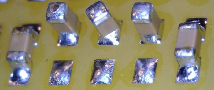
2. Tombstoning
Tombstoning is a defect where one end of a surface-mount component lifts off the pad during soldering, leaving the component standing upright like a tombstone. This often happens with small passive components like resistors and capacitors.
Causes:
- Uneven heating during reflow soldering, causing one pad to solidify before the other.
- Imbalanced pad design or unequal solder paste volume on the pads.
- Component placement errors or misalignment before soldering.
- Thermal mismatch between the component and the PCB material.
Impact: Tombstoning results in poor or no electrical connection, rendering the component non-functional and potentially affecting the entire circuit.
3. Component Misalignment
Component misalignment happens when a component is not placed correctly on its designated pads before or during the soldering process. This can result in skewed or shifted components that may not connect properly.
Causes:
- Inaccurate pick-and-place machine calibration or setup.
- PCB warpage or uneven surface affecting component placement.
- Vibration or movement during the assembly process.
- Incorrect component footprint design in the PCB layout.
Impact: Misaligned components can lead to poor solder joints, reduced reliability, or complete disconnection, especially in high-precision applications.
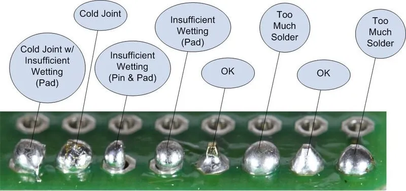
4. Insufficient Solder
Insufficient solder refers to a lack of solder material on a joint, resulting in weak or incomplete connections between the component and the PCB pad.
Causes:
- Inadequate solder paste deposition during stencil printing.
- Stencil clogging or wear, leading to uneven paste application.
- Improper reflow profile causing incomplete solder melting.
- Oxidation on pads or component leads preventing proper solder adhesion.
Impact: Weak solder joints can fail under mechanical stress or thermal cycling, leading to intermittent connections or complete circuit failure.
Troubleshooting SMT Assembly Defects: Practical Solutions
Now that we've identified the common SMT assembly defects and their causes, let's explore practical troubleshooting methods to address these issues effectively.
1. Addressing Solder Bridging
Solution:
- Optimize Stencil Design and Printing: Ensure the stencil apertures are correctly sized to avoid excess solder paste. Regularly clean and inspect stencils to prevent misalignment or clogging.
- Adjust Reflow Profile: Use a reflow oven temperature profile that prevents solder from flowing excessively. A typical peak temperature for lead-free solder is around 240-260°C, with a time above liquidus of 60-90 seconds.
- Improve Pad Spacing: During PCB design, ensure sufficient spacing between pads (at least 0.2mm for fine-pitch components) to minimize the risk of bridging.
- Manual Rework: For small-scale fixes, use a soldering iron with a fine tip and desoldering braid to remove excess solder.
2. Preventing Tombstoning
Solution:
- Balance Solder Paste Volume: Use automated inspection to ensure equal solder paste deposition on both pads of a component. Adjust stencil design if necessary.
- Optimize Reflow Profile: Ensure uniform heating by using a reflow profile with a gradual ramp-up rate (1-3°C per second) to prevent uneven solder melting.
- Check Component Placement: Verify pick-and-place machine accuracy to ensure components are centered on pads before soldering.
- Design Symmetry: Design pads with symmetrical shapes and sizes to promote even soldering on both ends of the component.
3. Correcting Component Misalignment
Solution:
- Calibrate Equipment: Regularly calibrate pick-and-place machines to ensure precise component placement. Check for wear in machine parts that could affect accuracy.
- Minimize PCB Warpage: Use rigid boards with balanced copper distribution and store PCBs in controlled environments to avoid moisture-induced warpage.
- Pre-Reflow Inspection: Conduct visual or automated checks after component placement to catch misalignments before soldering.
- Footprint Verification: Double-check PCB design files to ensure component footprints match the physical components being used.
4. Fixing Insufficient Solder
Solution:
- Inspect Solder Paste Printing: Use a solder paste inspection (SPI) system to verify paste volume and coverage before reflow. Typical paste height should be around 0.1-0.15mm for standard applications.
- Clean Pads and Leads: Ensure PCB pads and component leads are free of oxidation or contamination by using proper cleaning methods before assembly.
- Adjust Reflow Settings: Confirm the reflow profile provides adequate heat for complete solder melting, with a peak temperature suitable for the solder alloy used.
- Rework Joints: For existing defects, apply additional solder manually using a fine-tip soldering iron or hot air rework station.
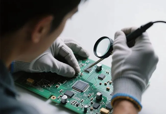
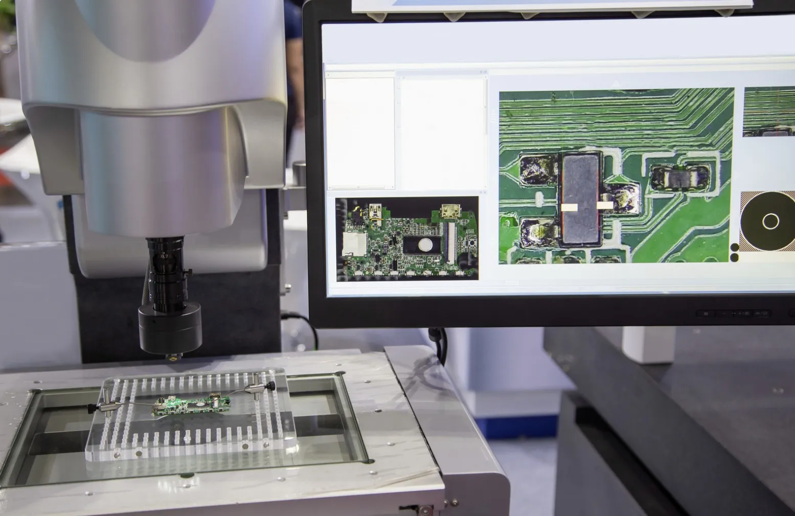
The Role of AOI Inspection in SMT Assembly
Automated Optical Inspection (AOI) is a critical tool for detecting SMT assembly defects in rigid board production. AOI systems use high-resolution cameras and advanced algorithms to inspect PCBs for issues like solder bridging, tombstoning, component misalignment, and insufficient solder.
Benefits of AOI Inspection in SMT:
- Early Defect Detection: AOI can identify defects immediately after soldering, reducing the risk of defective boards moving to later stages of production.
- High Accuracy: Modern AOI systems can detect defects as small as 0.01mm, ensuring even the tiniest issues are caught.
- Speed: AOI machines can inspect hundreds of boards per hour, far faster than manual inspection, making them ideal for high-volume production.
- Data Collection: AOI systems provide detailed reports on defect types and frequencies, helping manufacturers identify recurring issues and improve processes.
Implementation Tips:
- Integrate AOI inspection after the reflow soldering stage to catch defects early.
- Combine AOI with other inspection methods like X-ray for hidden joints or internal defects.
- Regularly update AOI software to ensure it recognizes new component types and defect patterns.
Preventive Measures for Long-Term Success
While troubleshooting is essential, preventing SMT assembly defects from occurring in the first place is even better. Here are some proactive steps to minimize issues in rigid board production:
- Design for Manufacturability (DFM): Follow DFM guidelines during PCB design to ensure pad sizes, spacing, and component placement are optimized for SMT assembly.
- Process Control: Implement strict controls for solder paste printing, component placement, and reflow soldering to maintain consistency across production runs.
- Training: Train assembly line operators on best practices for handling equipment and identifying potential issues before they escalate.
- Regular Maintenance: Schedule routine maintenance for all SMT equipment, including stencil printers, pick-and-place machines, and reflow ovens, to prevent mechanical failures.
- Quality Materials: Use high-quality solder paste, components, and PCB materials to reduce the likelihood of defects caused by inferior supplies.
Conclusion: Building a Defect-Free SMT Assembly Process
Troubleshooting common defects in rigid board SMT assembly, such as solder bridging, tombstoning, component misalignment, and insufficient solder, is crucial for maintaining product quality and production efficiency. By understanding the causes of these issues and implementing practical solutions, manufacturers can significantly reduce rework costs and improve reliability. Additionally, leveraging tools like AOI inspection in SMT ensures defects are caught early, saving time and resources in the long run.
At ALLPCB, we are committed to supporting your SMT assembly needs with high-quality materials, advanced inspection techniques, and expert guidance. By following the tips and strategies outlined in this guide, you can tackle SMT assembly defects head-on and achieve consistent, high-performing results in your rigid board production.
Start applying these troubleshooting and prevention methods today to build a more efficient and reliable SMT assembly process!


