 ALLPCB


Through-Hole Technology (THT) remains a vital method in Printed Circuit Board Assembly (PCBA) for specific applications where durability and reliability are paramount. If you're searching for insights on THT PCBA assembly, through-hole components, THT soldering techniques, THT design considerations, or a comparison of THT vs SMT, you're in the right place. This blog dives deep into the world of THT, offering practical advice and best practices to help engineers and designers make informed decisions for their projects.
In this comprehensive guide, we'll explore what THT is, its key applications, design tips, soldering methods, and how it stacks up against Surface Mount Technology (SMT). Whether you're working on high-power electronics or prototyping, understanding THT can elevate the quality of your assemblies. Let's get started!
What is Through-Hole Technology (THT) in PCBA?
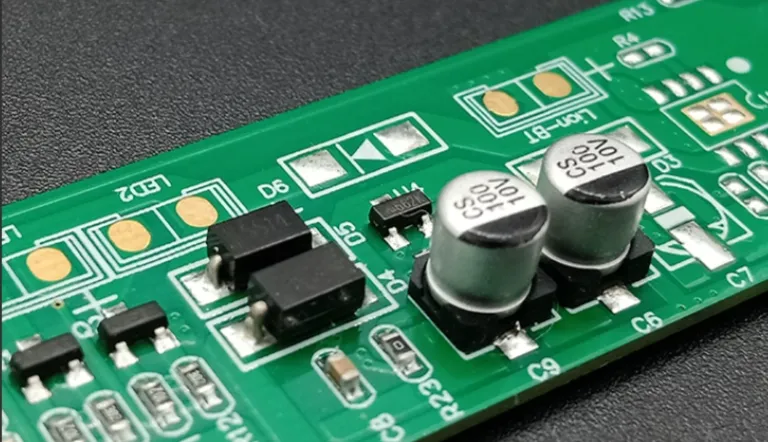
Through-Hole Technology, often abbreviated as THT, is a traditional method of mounting electronic components onto a printed circuit board (PCB). In THT PCBA assembly, component leads are inserted through pre-drilled holes on the PCB and soldered to pads on the opposite side. This creates a strong mechanical bond, making THT ideal for applications that require robust connections.
Introduced in the 1950s, THT was the dominant PCB assembly technique until the rise of Surface Mount Technology (SMT) in the 1980s. Despite SMT's popularity for compact designs, THT continues to hold a significant place in industries where reliability under stress is critical. Think of large connectors, power components, or devices exposed to vibrations—those often rely on through-hole components for their stability.
Key Applications of Through-Hole Technology in PCBA
THT is not a one-size-fits-all solution, but it excels in specific scenarios. Here are some common applications where through-hole components shine:
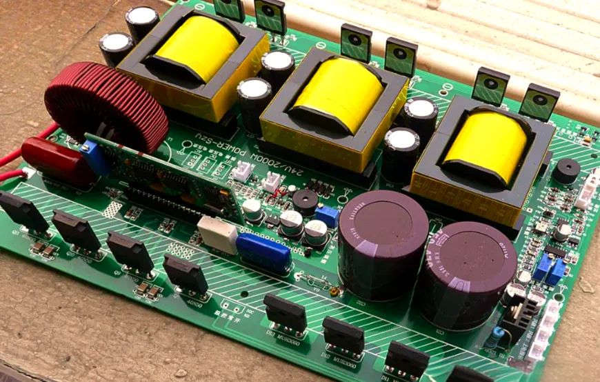
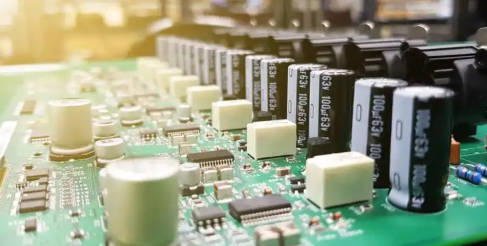
- High-Power Electronics: Components like transformers, large capacitors, and power resistors often use THT due to their size and the need for secure mounting. These parts handle high currents, sometimes exceeding 10A, and THT ensures they stay in place under thermal or mechanical stress.
- Industrial Equipment: Machinery in harsh environments, such as factory automation systems, relies on THT for its ability to withstand vibrations and temperature swings. A soldered through-hole connection can endure forces up to 100N without breaking, far surpassing typical SMT bonds.
- Prototyping and Testing: During the design phase, engineers often prefer THT components because they are easier to manually insert, remove, or replace on breadboards or prototype PCBs. This flexibility speeds up iterations.
- Aerospace and Automotive: In sectors where failure is not an option, THT provides the reliability needed for critical systems. Components in these fields must resist shocks and maintain integrity over years of use.
While THT may not suit ultra-compact consumer electronics, its mechanical strength makes it indispensable in these specialized areas.
Advantages of THT in PCBA Assembly
Understanding the benefits of THT helps in deciding when to use it over other methods. Here’s why THT PCBA assembly remains relevant:
- Mechanical Durability: The physical insertion of leads through holes and soldering on the other side creates a robust connection. This is especially important for components subject to stress or frequent handling.
- Ease of Repair: Through-hole components are simpler to desolder and replace compared to tiny SMT parts. This makes THT a go-to for designs where maintenance is expected.
- High Heat Tolerance: THT components can handle higher temperatures during operation or soldering, often up to 260°C, without risking damage to the connection.
- Better for High-Voltage Applications: The spacing and insulation provided by THT layouts reduce the risk of arcing in circuits operating above 100V.
These advantages make THT a reliable choice for projects where stability trumps size constraints.
Challenges of Using Through-Hole Technology
Despite its strengths, THT has limitations that designers must consider during THT PCBA assembly:
- Larger Footprint: Through-hole components take up more space on a PCB compared to SMT parts, limiting their use in compact devices. A typical through-hole resistor might occupy 10 times the area of an SMT equivalent.
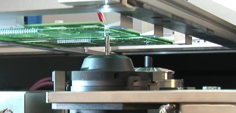
- Slower Assembly Process: Drilling holes and manually or automatically inserting components adds time to production. Automated THT insertion machines operate at speeds of about 200-400 components per hour, far slower than SMT pick-and-place machines, which can place thousands per hour.
- Higher Costs for Mass Production: The additional steps in THT assembly, combined with the need for larger boards, increase manufacturing costs, especially for high-volume runs.
Balancing these challenges with the benefits is key to determining if THT fits your project needs.
THT vs SMT: A Detailed Comparison
When choosing between THT and Surface Mount Technology (SMT), understanding their differences is crucial. Here’s a breakdown of THT vs SMT to guide your decision:
- Size and Space: SMT components are much smaller, often less than 1mm in some dimensions, allowing for denser PCB layouts. THT parts, with leads and holes, require more board real estate, making them less ideal for compact designs like smartphones.
- Assembly Speed: SMT dominates in automated, high-speed production, with placement rates reaching 50,000 components per hour. THT assembly, even when automated, is slower due to the insertion and soldering steps.
- Durability: THT connections are stronger mechanically, ideal for heavy or stressed components. SMT, while efficient, can fail under physical strain, with solder joints breaking under forces as low as 10N.
- Cost: SMT is generally cheaper for large-scale production due to automation and smaller board sizes. THT can be more cost-effective for low-volume or prototype runs where manual assembly is common.
- Applications: Use THT for high-power, high-reliability needs like industrial controls. Opt for SMT in consumer electronics where size and speed matter most.
In many modern designs, a hybrid approach combining THT and SMT is used to leverage the strengths of both. For instance, a PCB might use SMT for small ICs and THT for connectors or power components.
THT Design Considerations for Optimal PCBA
Designing a PCB for THT PCBA assembly requires attention to detail to ensure reliability and manufacturability. Here are key THT design considerations:
- Hole Size and Spacing: Ensure drilled holes match component lead diameters, typically ranging from 0.7mm to 1.5mm, with a tolerance of ±0.05mm. Too tight, and insertion becomes difficult; too loose, and solder may not fill properly. Maintain at least 2mm spacing between holes to prevent interference.
- Pad Size: Pads for through-hole soldering should be 1.5 to 2 times the hole diameter to allow adequate solder flow. For a 1mm hole, aim for a 1.5mm to 2mm pad.
- Thermal Relief: For multilayer boards, use thermal relief patterns around holes to prevent heat dissipation issues during soldering. This ensures even heating, avoiding cold solder joints.
- Component Placement: Place through-hole components on one side of the board if possible to simplify wave soldering. Group similar components together to streamline assembly.
- Board Thickness: Use a PCB thickness of at least 1.6mm for THT to provide structural support for inserted components, especially larger ones like connectors.
Following these guidelines during the design phase can save time and reduce errors during assembly.
THT Soldering Techniques for Reliable Connections
Soldering is a critical step in THT PCBA assembly, directly impacting the quality of the final product. Here are proven THT soldering techniques:
- Manual Soldering: For small runs or repairs, manual soldering with a 25-40W iron at 300°C is effective. Apply solder to the pad and lead simultaneously for 2-3 seconds to create a shiny, cone-shaped joint. Avoid overheating, as it can damage components or lift pads.
- Wave Soldering: Ideal for mass production, wave soldering involves passing the PCB over a molten solder wave at 260°C. Pre-flux the board to improve wetting, and ensure leads are trimmed to 1-2mm above the board to prevent excess solder buildup.
- Selective Soldering: For mixed THT and SMT boards, selective soldering targets specific through-hole areas with a mini solder fountain. This method minimizes thermal stress on nearby SMT components.
- Inspection: After soldering, inspect joints for cold solder (dull appearance) or insufficient fill. A good joint covers at least 75% of the pad and hole with a smooth finish.
Using the right technique based on production volume and board complexity ensures strong, lasting connections.
Best Practices for THT PCBA Assembly
To achieve high-quality results with THT, follow these best practices during assembly:
- Component Preparation: Trim and bend leads to fit hole patterns before insertion. Use forming tools for consistency, especially for axial components like resistors, to avoid stress on leads.
- Cleanliness: Keep the PCB and components free of dust or grease before soldering. Use isopropyl alcohol and a brush to clean surfaces, ensuring better solder adhesion.
- Temperature Control: Monitor soldering temperatures closely. For lead-free solder, maintain a range of 260-270°C to prevent thermal shock to components or board materials.
- Post-Assembly Testing: Conduct electrical tests to verify connections. Use a multimeter to check for continuity across soldered joints, ensuring no open circuits exist.
- Documentation: Maintain clear records of component placement and soldering parameters for traceability, especially in regulated industries like aerospace.
These steps help minimize defects and ensure your THT assemblies meet performance standards.
Future Trends in Through-Hole Technology
While SMT dominates modern electronics, THT is not fading away. Innovations like hybrid PCB designs, combining THT for strength and SMT for density, are gaining traction. Additionally, advancements in automated THT insertion machines are speeding up assembly, narrowing the gap with SMT in some low-volume scenarios. Research into new soldering materials, such as low-temperature alloys, also promises to enhance THT's performance in high-reliability applications.
As industries like automotive and renewable energy grow, with a projected PCB market value of $125 billion by 2028, THT will continue to play a key role where durability cannot be compromised.
Conclusion: Leveraging THT for Reliable PCBA
Through-Hole Technology (THT) in PCBA assembly offers unmatched reliability for applications requiring mechanical strength and durability. From high-power electronics to industrial systems, THT provides a robust solution despite its larger footprint and slower assembly compared to SMT. By understanding THT design considerations, mastering THT soldering techniques, and applying best practices, engineers can optimize their designs for performance and longevity.
Whether you're weighing THT vs SMT or planning a project with through-hole components, the insights shared here can guide your process. With careful planning and execution, THT remains a powerful tool in the ever-evolving world of electronics manufacturing. Trust in its proven track record to deliver results where it matters most.


