ALLPCB


When designing a printed circuit board (PCB), one of the key decisions is choosing the right type of indicator lights. Should you go with Surface-Mount Device (SMD) LEDs or Through-Hole LEDs? Both technologies have their unique strengths and are suited for different applications in PCB assembly. In this comprehensive guide, we’ll break down the differences between SMD and Through-Hole indicator lights, focusing on SMD LED advantages, Through-Hole LED benefits, PCB assembly indicator choices, SMT indicator lights, and LED mounting techniques. By the end, you’ll have a clear understanding of which technology best fits your project needs.
Quick Answer: Which Indicator Light Technology Should You Choose?
For most modern PCB designs, SMD LEDs are the go-to choice due to their compact size, energy efficiency, and compatibility with automated assembly processes. However, Through-Hole LEDs are ideal for applications requiring durability, easy manual repairs, or high-power output. The decision depends on your project’s specific requirements, such as space constraints, budget, and manufacturing capabilities. Let’s dive deeper into each technology to help you make an informed choice.
What Are Indicator Lights in PCB Design?
Indicator lights, typically LEDs (Light Emitting Diodes), are small components used on PCBs to signal status, power, or operational conditions. For instance, a green LED might indicate that a device is powered on, while a red one could signal an error. These lights are essential for user interaction and diagnostics in electronic devices. When selecting indicator lights for PCB assembly, the two primary mounting technologies are SMD and Through-Hole. Each method affects the design, manufacturing process, and performance of the final product.
Understanding SMD Indicator Lights
SMD LEDs are tiny components mounted directly onto the surface of a PCB using Surface-Mount Technology (SMT). They are widely used in modern electronics due to their small footprint and efficiency. Let’s explore the key aspects of SMT indicator lights and why they might be the right choice for your design.
SMD LED Advantages
SMD LEDs come with several benefits that make them a popular choice for PCB assembly indicators:
- Compact Size: SMD LEDs are incredibly small, often measuring just a few millimeters (e.g., 1.6mm x 0.8mm for a 0603 package). This allows for high-density designs, saving valuable space on the PCB, which is crucial for compact devices like smartphones or wearable tech.
- Energy Efficiency: These LEDs consume less power compared to many Through-Hole counterparts, often operating at low currents (e.g., 20mA or less) while still providing sufficient brightness for indicator purposes.
- Automation-Friendly: SMD components are designed for automated pick-and-place machines, reducing assembly time and labor costs in large-scale production. This can cut manufacturing time by up to 50% compared to manual soldering.
- Variety of Colors and Configurations: SMD LEDs are available in a wide range of colors (red, green, blue, etc.) and even multi-color options in a single package, offering flexibility for indicator designs.
- Low Profile: Their flat design ensures they don’t protrude much from the board, making them ideal for sleek, modern enclosures.
Challenges with SMD LEDs
While SMD LEDs have many advantages, they also come with some limitations:
- Difficult Repairs: Due to their small size, replacing or repairing SMD LEDs requires specialized tools like hot air rework stations, making manual fixes challenging.
- Lower Durability in Harsh Conditions: SMD LEDs are more susceptible to damage from vibration or mechanical stress compared to Through-Hole LEDs, which can be an issue in industrial applications.
- Heat Management: In high-power applications, heat dissipation can be a concern since SMD LEDs are mounted directly on the board with limited surface area for cooling.
Understanding Through-Hole Indicator Lights
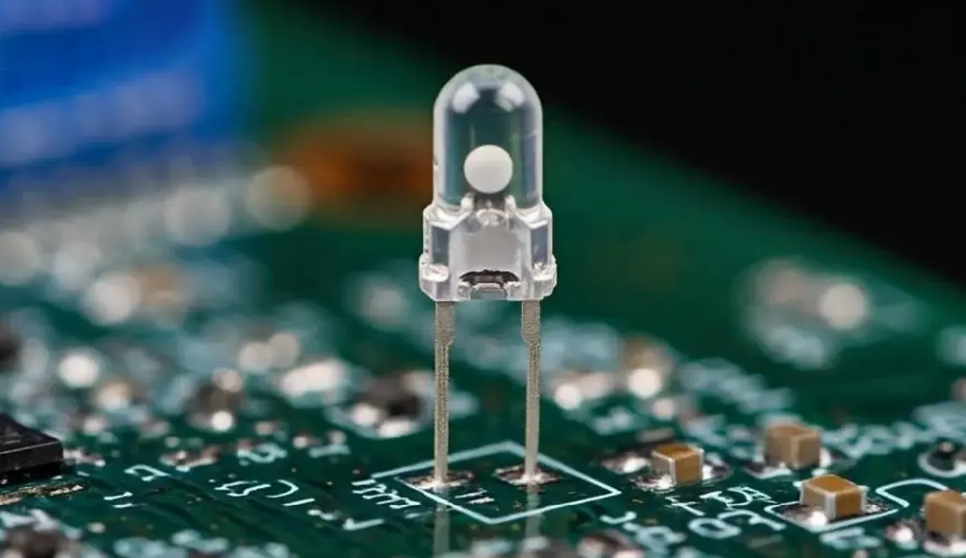
Through-Hole LEDs are traditional components with leads that pass through holes in the PCB and are soldered on the opposite side. This mounting technique has been used for decades and remains relevant for specific applications. Let’s look at the key features of Through-Hole LEDs.
Through-Hole LED Benefits
Through-Hole LEDs offer distinct advantages that make them suitable for certain PCB designs:
- Durability: The leads of Through-Hole LEDs provide strong mechanical bonding to the PCB, making them more resistant to vibration and physical stress. This is ideal for applications in automotive or industrial environments where reliability is critical.
- Easy to Replace: Their larger size and leaded design make Through-Hole LEDs simpler to desolder and replace manually, even without advanced tools. This is a significant advantage for prototyping or small-scale repairs.
- Higher Power Handling: Through-Hole LEDs can often handle higher currents (e.g., up to 100mA or more) and are better suited for applications requiring brighter output or larger indicator lights visible from a distance.
- Better Heat Dissipation: The leads and larger body of Through-Hole LEDs allow for better heat dissipation compared to SMD LEDs, reducing the risk of overheating in high-power scenarios.
- Cost-Effective for Small Runs: For low-volume production or manual assembly, Through-Hole components can be cheaper since they don’t require expensive automated equipment.

Challenges with Through-Hole LEDs
Despite their benefits, Through-Hole LEDs have some drawbacks:
- Larger Size: These LEDs take up more space on the PCB, both in terms of footprint and height (often protruding 5-10mm above the board), making them unsuitable for compact designs.
- Manual Assembly: Through-Hole components often require manual soldering, which increases labor costs and assembly time, especially in high-volume production.
- Limited Design Flexibility: They cannot be mounted on both sides of the PCB as easily as SMD components, restricting design options in dense layouts.
Comparing SMD and Through-Hole for PCB Assembly Indicators
Choosing between SMD and Through-Hole indicator lights depends on several factors related to your PCB design and application. Let’s compare them across key criteria to help you decide.
| Criteria | SMD LEDs | Through-Hole LEDs |
|---|---|---|
| Size | Very small (e.g., 1.6mm x 0.8mm) | Larger (e.g., 3-5mm diameter) |
| Assembly Method | Automated (SMT) | Manual or semi-automated |
| Durability | Less resistant to stress | Highly durable under stress |
| Power Handling | Lower (e.g., 20-50mA) | Higher (e.g., up to 100mA) |
| Repairability | Difficult, needs special tools | Easy, minimal tools required |
| Cost (High Volume) | Lower due to automation | Higher due to labor |

LED Mounting Techniques for PCB Design
The way LEDs are mounted on a PCB significantly impacts the manufacturing process and the final product’s performance. Here are the primary LED mounting techniques for both SMD and Through-Hole indicator lights.
Surface-Mount Technology (SMT) for Indicator Lights
SMT is used for mounting SMD LEDs directly onto the PCB surface. The process involves:
- Applying solder paste to the PCB pads using a stencil.
- Placing SMD LEDs onto the pads using automated pick-and-place machines.
- Heating the board in a reflow oven to melt the solder and secure the components.
This method is highly efficient for mass production, achieving placement rates of up to 100,000 components per hour in industrial setups. However, it requires precise design files and specialized equipment.
Through-Hole Mounting Technique
Through-Hole mounting involves inserting the LED leads through pre-drilled holes in the PCB and soldering them on the opposite side. The process includes:
- Drilling holes in the PCB at specified locations.
- Inserting the Through-Hole LED leads into the holes, often manually.
- Soldering the leads to the pads, either by hand or using wave soldering for larger batches.
This technique is slower, with manual soldering taking several seconds per component, but it ensures a strong mechanical connection.

When to Choose SMD LEDs for Your PCB
Opt for SMD LEDs in these scenarios:
- Your design requires a compact layout with limited space for components.
- You’re producing high volumes, and automation can reduce costs and time.
- The application doesn’t involve harsh conditions like extreme vibration or mechanical stress.
- Energy efficiency and a sleek design are priorities.
For example, in consumer electronics like smartwatches, SMD LEDs are often used as status indicators due to their small size and low power consumption (typically 2-3V at 20mA).
When to Choose Through-Hole LEDs for Your PCB
Choose Through-Hole LEDs under these conditions:
- Your project involves prototyping or small-batch production where manual assembly is feasible.
- The application demands high durability, such as in industrial control panels or automotive systems.
- You need brighter indicators or higher power handling for visibility over long distances.
- Easy repair and replacement are important for maintenance purposes.
For instance, in a factory control board, a 5mm Through-Hole LED operating at 3.2V and 30mA might be used to signal machine status clearly from across a room.
Final Thoughts on Choosing the Right Indicator Light Technology
Selecting between SMD and Through-Hole indicator lights for your PCB assembly comes down to balancing design constraints, manufacturing capabilities, and application needs. SMD LEDs shine in modern, compact, and high-volume projects thanks to their size, efficiency, and compatibility with automated processes. On the other hand, Through-Hole LEDs remain a reliable choice for durability, ease of repair, and high-power applications, especially in rugged environments.
By understanding the SMD LED advantages, Through-Hole LED benefits, and the specifics of LED mounting techniques, you can make an informed decision that optimizes both performance and cost. Whether you’re designing a cutting-edge gadget or a robust industrial system, the right PCB assembly indicator technology will enhance your product’s functionality and user experience.