ALLPCB


Overview of Modbus
Modbus is a serial communication protocol first published by Modicon in 1979 for communication between programmable logic controllers (PLC). It has become an industry standard for industrial communication and is commonly used to connect industrial electronic devices.
Modbus employs a master-slave communication model in which the master initiates queries and operations on slave devices. The protocol used by the master is referred to as Modbus Master; the protocol used by the slaves is referred to as Modbus Slave. Typical masters include industrial PCs and controllers; typical slaves include PLCs.
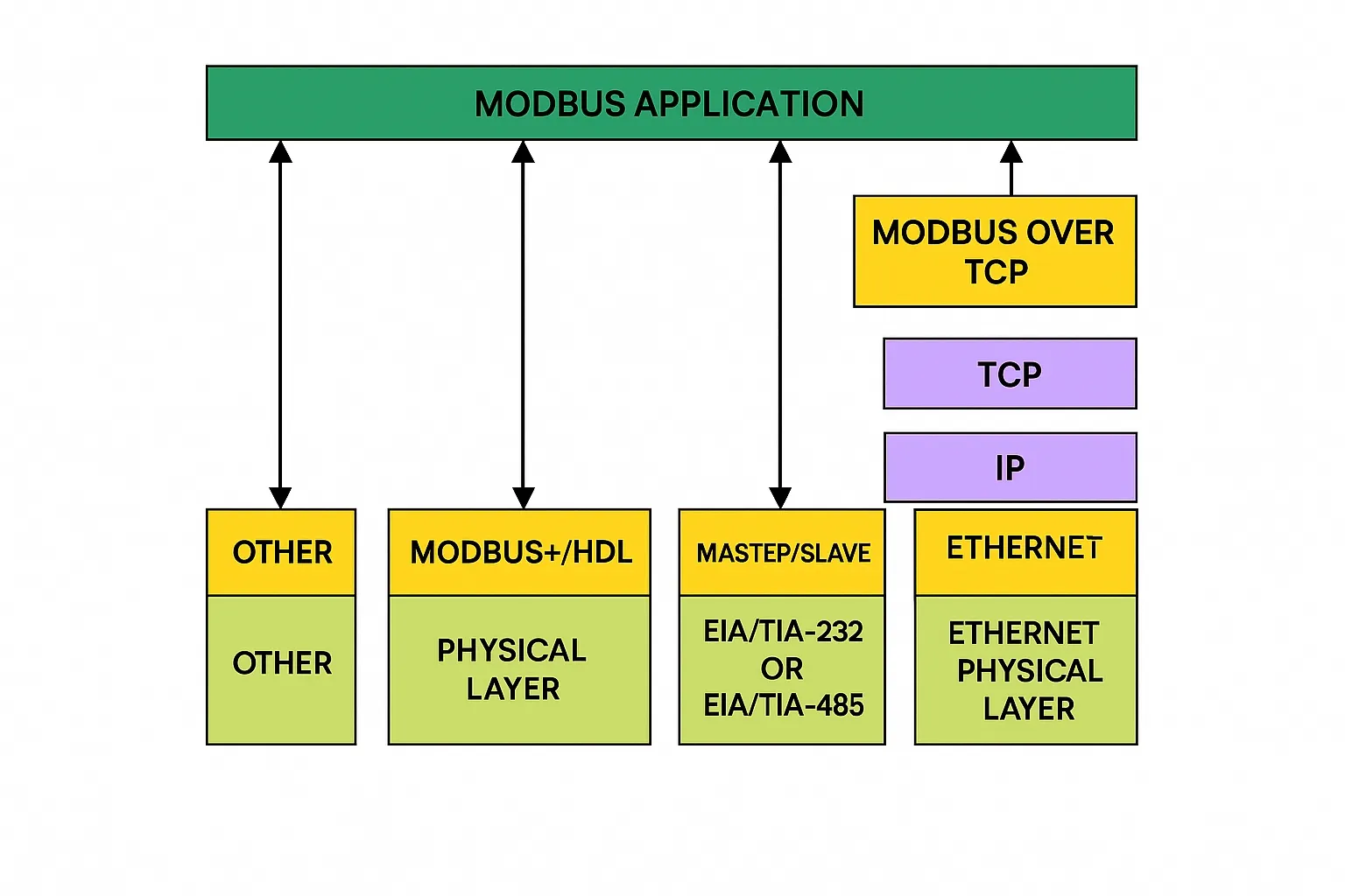
Modbus is an application layer protocol on the OSI model. It provides client/server communication between devices connected over different physical buses or networks. Physical interfaces for Modbus include serial ports (RS232, RS485) and Ethernet.
Figure 1. Modbus communication stack
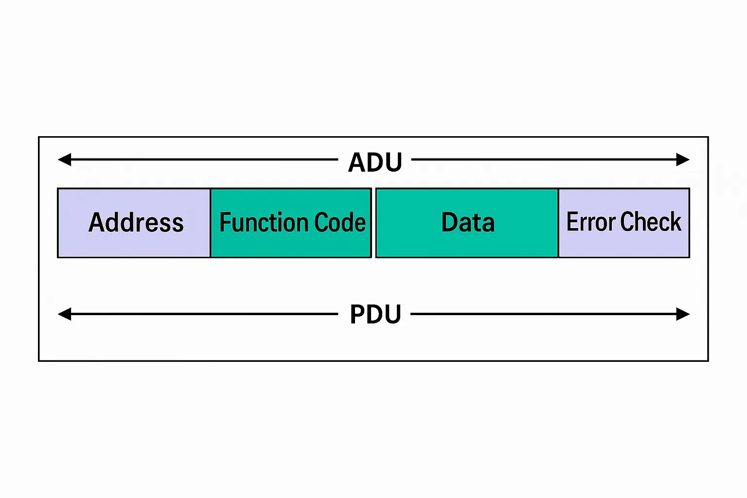
Modbus defines a simple Protocol Data Unit (PDU) independent of the underlying communication layer. Specific mappings for a given bus or network may introduce additional fields to the Application Data Unit (ADU).
Figure 2. General Modbus frame
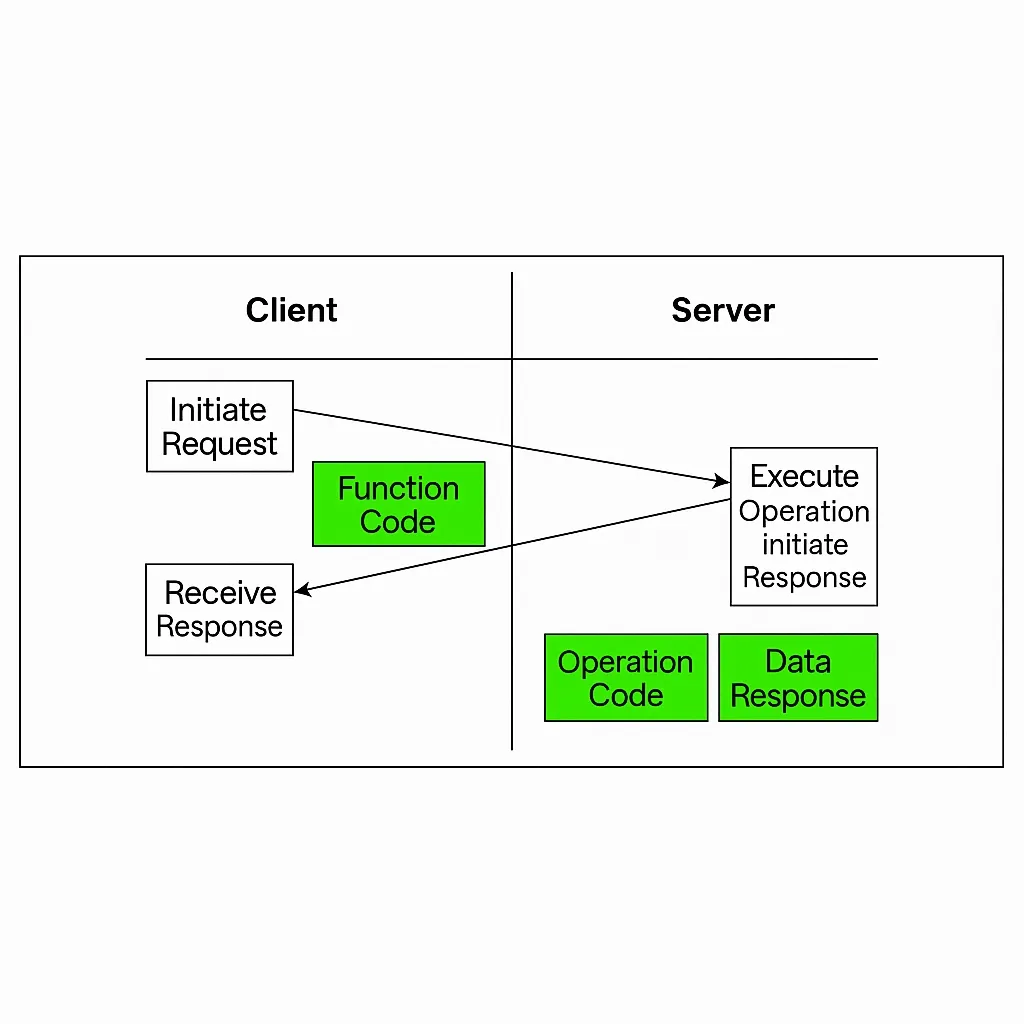
When a slave responds to a request, the function code field indicates either a normal (no-error) response or an error (exception) response. Implementations must handle timeouts to account for missing replies.
Figure 3. Modbus transaction (no error)
Modbus uses big-endian byte order for addresses and data items. For example, a 16-bit register value 0x1234 is transmitted as 0x12 followed by 0x34.
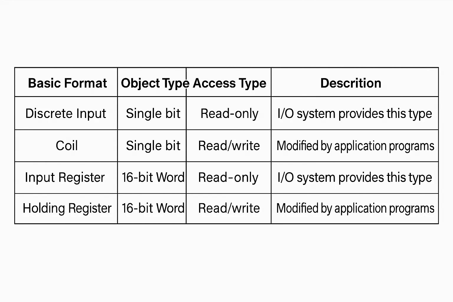
The Modbus data model is based on four basic tables with different characteristics:
Form1: Modbus data model
Function codes in Modbus are grouped into three categories: public function codes, user-defined function codes, and reserved function codes. Public function codes are well-defined, unique, and intended for interoperability and consistent testing.
Modbus serial links implement a master-slave protocol. At any time only one master is connected to the bus; one or more slaves (up to 247) may be connected to the same serial bus. Communication is always initiated by the master. Slaves do not transmit without a request from the master, and slaves do not communicate with each other. The master may initiate one Modbus transaction at a time.
The master can address slaves in two modes:
- Unicast: The master addresses a specific slave. The addressed slave processes the request and returns a response. Each slave must have a unique address (1 to 247) to be individually addressed.
- Broadcast: The master sends a request to all slaves. Broadcast requests do not produce a reply and are typically used for write commands. All devices should accept broadcast write functions. Address 0 is reserved for broadcast.
Two serial transmission modes are defined for Modbus: RTU (default) and ASCII.
Figure 4. Bit sequences for RTU and ASCII modes
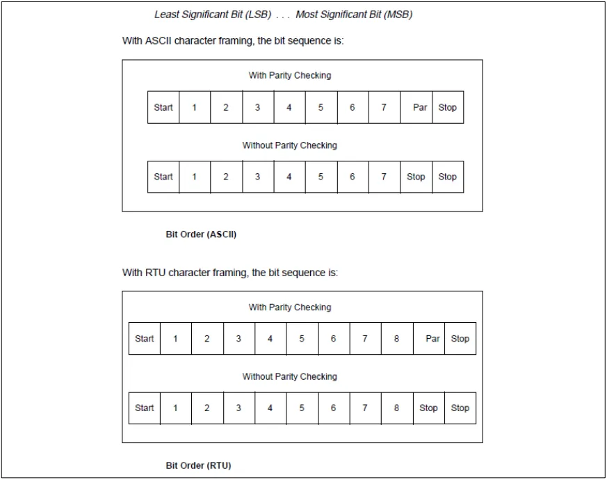
All devices on a Modbus serial link must use the same transmission mode and serial port parameters.
About FreeMODBUS
FreeMODBUS is an implementation of the Modbus protocol stack for embedded systems. It supports RTU/ASCII modes and TCP. FreeMODBUS is distributed under the BSD license, which permits commercial use. The freely available distribution contains a Modbus slave stack. The stack is written in ANSI C and supports multiple variables.
This guide describes how to implement a Modbus slave using the FreeMODBUS stack on an AT32F435 microcontroller. It includes source code based on AT32F43x_StdPeriph_Lib and FreeMODBUS. Using AT32-Comm-EV Board and an AT-START board simplifies building an RS485-based Modbus slave node.
Modbus Poll Host Tool
Modbus Poll is a Modbus master simulator that supports Modbus RTU, ASCII, and TCP/IP. It helps developers test and debug Modbus slave devices by simulating master requests. Multiple slave devices and data areas can be monitored simultaneously. Each window configures slave ID, function code, address, length, and poll interval. Modbus Poll supports the four Modbus data tables and common public function codes.
In this guide, Modbus Poll is used on a PC as the Modbus master. The AT-START board acts as the slave and connects via a USB-to-RS485 module to form a complete, testable Modbus network.
AT32 Hardware Setup
Hardware for the demo consists primarily of the AT32-Comm-EV Board and the AT-START Board.
The demo uses peripherals such as USART and TMR. Developers may reconfigure these resources as needed. Modbus physical layer can be implemented over RS232 or RS485.
Figure 9. AT32 Modbus system diagram
AT-START Board
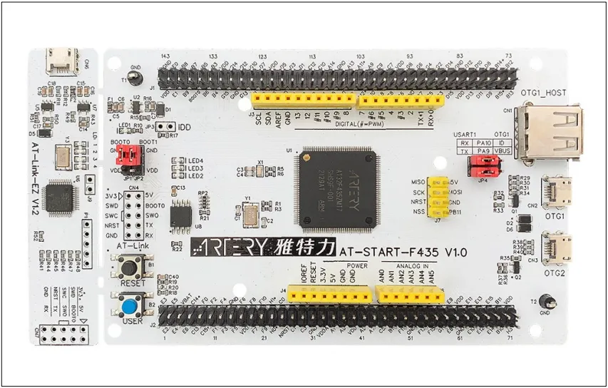
The provided example is based on AT-START-F435 and supports RS232-based Modbus communication.
Figure 10. AT-START-F435 V1.0 evaluation board
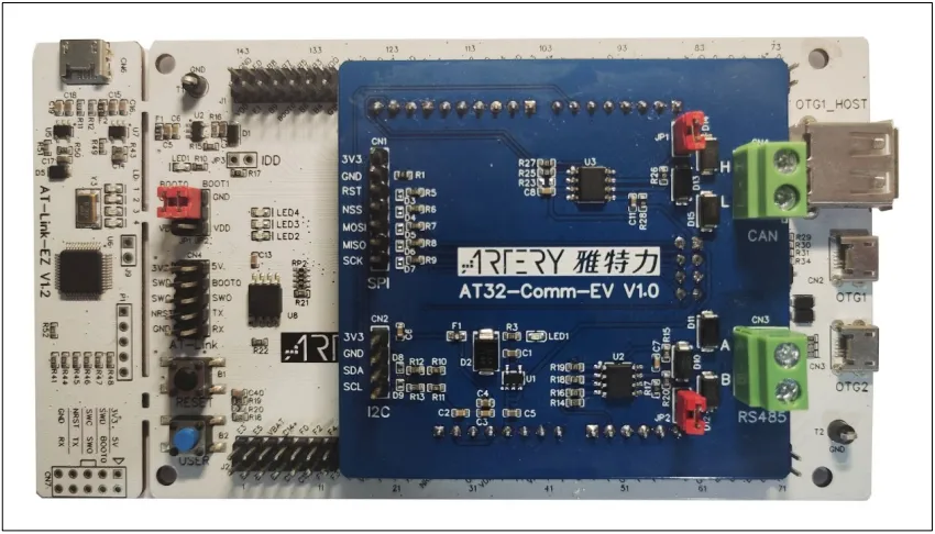
AT32-Comm-EV Board
This board provides RS485 support for the example.
Figure 11. AT-START used with AT32-Comm-EV
Porting FreeMODBUS to AT32
Project preparation
Download the BSP and PACK files for the target platform and follow their installation and configuration instructions. The examples in this guide were developed against AT32F4xx_StdPeriph_Lib_V2.x.x. Use the at_start_f435 example as a starting point: copy and rename the folder and project to freemodbus, and prepare to add the FreeMODBUS source code.
Adding FreeMODBUS source
Obtain the latest FreeMODBUS source from the FreeMODBUS website or GitHub. This guide and provided examples are based on freemodbus-v1.6.
Figure 12. FreeMODBUS source files
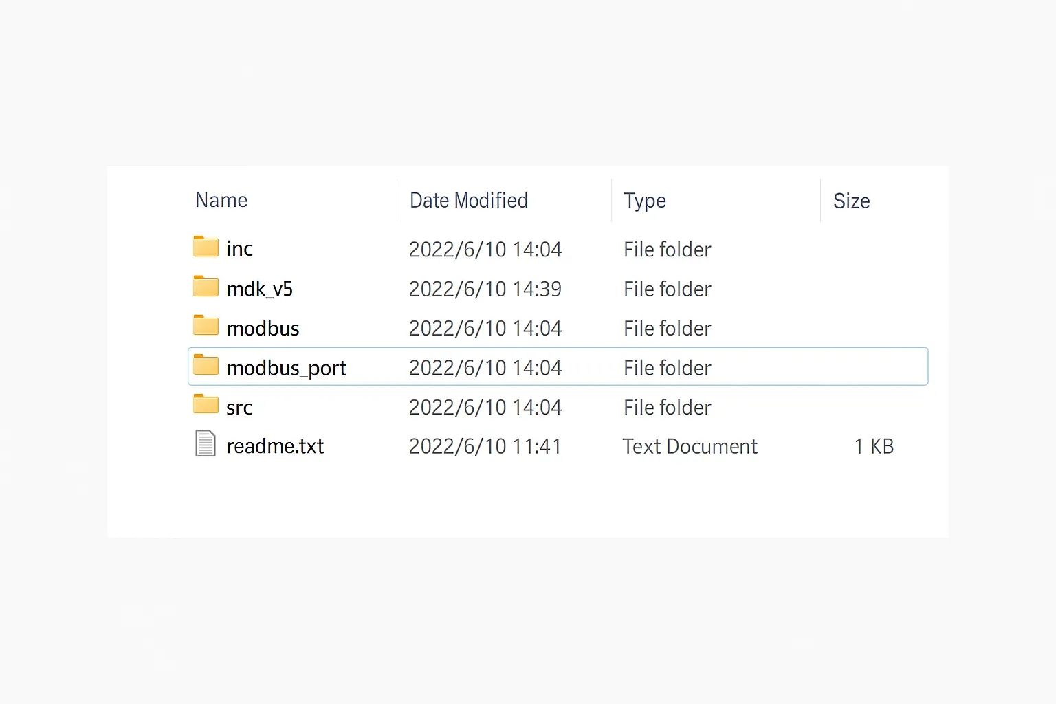
After extracting the source, copy the modbus folder and the demoBAREport folder into the freemodbus project directory. Rename the port folder to modbus_port. Example directory structure:
Figure 13. freemodbus project directory
Open the project file and add the following:
- Add all .c files from modbus and modbus_port to the project, excluding TCP-related files.
- Add the include paths for the corresponding .h files to the project folder settings.
Source code modifications
- Edit port.h: include the AT32 MCU header at32f435_437.h, provide macros for critical-section handling (interrupt disable/enable) used for mutual exclusion, and comment out TRUE/FALSE macro definitions to avoid conflicts with definitions in the AT BSP headers.
- Edit portserial.c and porttimer.c: implement low-level drivers for USART and TMR peripherals according to your hardware. Refer to vendor examples for guidance.
- Note: The USART data register on this MCU may contain both data bits and parity bits. FreeMODBUS expects the data register to contain only data bits, so adjust the receive handling to extract data correctly. See vendor example code and modify mbascii.c accordingly.
- Create mbtask.c and mbtask.h in the project. These implement a Modbus communication task that calls the FreeMODBUS API and establishes the Modbus data model (the four basic tables) for communication testing with Modbus Poll.
The mbtask implementation should provide handlers for:
- Reading and writing holding registers
- Reading input registers
- Reading and writing coils
- Reading discrete inputs
mbtask.h defines the Modbus data model and parameters required to initialize communication.
Figure: Modbus configuration parameters
Implementing device functionality
- Implement void modbus_task(void) in mbtask.c to invoke the protocol stack APIs and implement the Modbus slave task.
- Call modbus_task() from main in main.c to start the Modbus task.
Testing
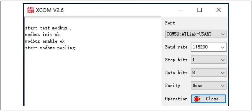
After completing the port and building the example, program the MCU and open the serial terminal connected through AT-Link. The firmware prints status messages indicating that the slave is running.
Figure: Serial console output
Connect the device to a PC running Modbus Poll via USB-to-RS485 converter and configure Modbus Poll to match the slave's transport mode (RTU) and serial parameters. Define read/write commands in Modbus Poll. For example, use function code 03 to read holding registers. If configured correctly, Modbus Poll should read the initialized holding register values from the slave, confirming correct operation.