ALLPCB


Introduction
In modern industrial automation and automotive electronics, the CAN bus is a leading choice for communication due to its high reliability and real-time performance. CANopen, a higher-layer communication protocol built on the CAN bus, is widely used for communication between various devices. This article describes how to port the CANopenNode protocol stack to the MindMotion MM32G5330 MCU using its FlexCAN peripheral. The process is validated on the Mini-G5333 development board.
CANopen Overview
CANopen is a higher-layer communication protocol developed by the CiA (CAN-in-Automation) organization. It defines a set of communication objects for industrial automation and implements functions such as network management, device configuration, and data exchange on top of the CAN bus. The CANopen protocol standardizes how devices communicate over the CAN bus, enabling seamless integration and interoperability between devices from different manufacturers.
The structure of CANopen from the application to the CAN bus includes:
- Application Layer: Implements various application objects.
- Object Dictionary (OD): Describes the parameters of a CANopen node device.
- Communication Interface: Defines the communication rules of the CANopen protocol and the mapping to the CAN controller driver.
Three communication models are used in a CANopen network:
- Master/Slave Model: One node (e.g., a control interface) acts as the application master controller, while slave nodes (e.g., servo motors) send or request data. This model is generally used for diagnostics or state management.
- Client/Server Model: A client sends a data request to a server, which then responds. This is used, for example, when an application master needs data from a slave's Object Dictionary.
- Producer/Consumer Model: A producer node broadcasts data to the network, which is then consumed by consumer nodes. The producer can send this data upon request or without a specific request.
CANopen defines seven message types:
- NMT (Network Management): Controls the state of CANopen devices for network management.
- SYNC (Synchronization): SYNC messages are used to synchronize input sensing and drive actions across multiple CANopen devices, typically triggered by an application master.
- EMCY (Emergency): Used when a device encounters an error (e.g., a sensor failure) to transmit an internal error code.
- TIME (Time Stamp): Distributes network time. It is typically broadcast without requiring a node acknowledgment, using CAN-ID 0x100 and a 6-byte data length representing the time difference from 00:00 on January 1, 1984. Nodes store this time in index 0x1012 of the Object Dictionary.
- PDO (Process Data Object): The PDO service is used for transmitting real-time data between devices, such as measurement data (e.g., position) or command data (e.g., torque request).
- SDO (Service Data Object): Used to access or change values in a CANopen device's Object Dictionary—for example, when an application master needs to change a device's configuration.
- Heartbeat: The Heartbeat service has two purposes: providing a "liveliness" message and confirming NMT commands.
The CANopenNode Protocol Stack
CANopenNode is a free and open-source CANopen protocol stack written in ANSI C in an object-oriented style. It can run on various microcontrollers, either as a standalone application or with an RTOS. Variables (communication, device, custom) are collected in the CANopen Object Dictionary and can be modified in two ways: through the C source code and over the CANopen network.
The CANopenNode homepage is located at:
https://github.com/CANopenNode/CANopenNode
CANopenNode vs. CANFestival
Both CANopenNode and CANFestival are open-source software stacks for implementing CANopen protocol communication on embedded systems. They use different open-source licenses. CANFestival uses the LGPLv2 license, which means that while its source code is freely available for use, modification, and distribution, any derivative works must also be licensed under the same GPL license. If a company uses CANFestival in a product, they must also provide the source code of their product under the LGPLv2 license. In contrast, CANopenNode uses the Apache v2.0 license, which is more permissive than LGPLv2 and allows for greater flexibility. Anyone can use, modify, and distribute CANopenNode, even for commercial purposes, without being required to release the source code of their derivative works.
Pre-Porting Preparation
Get the CANopenNode Source Code
Select CANopenNode v1.3, an official release version. The source code can be obtained from:
https://github.com/CANopenNode/CANopenNode/releases/tag/v1.3
Get MiniBoard-OB (MM32G5333D6QV) Examples and Board Data
Details about the development board and LibSamples are available on the MindMotion website.
Compiler and Development Environment
The project is created using Keil MDK-ARM.
Porting CANopenNode using FlexCAN
The CANopenNode porting process involves copying, referencing, and modifying three files:
-
CANopenNode-1.3/example/main.c
-
CANopenNode-1.3/stack/drvTemplate/CO_driver.c
-
CANopenNode-1.3/stack/drvTemplate/CO_driver_target.h
The key modifications are:
- In main.c, implement the
tmrTask_thread()function: This function is called from a 1ms timer interrupt service routine for 1ms time-based synchronization. - In CO_driver.c, implement the
CO_CANmodule_init()function: This function initializes the MCU's CAN module, configures CAN message reception and transmission parameters, and enables the FlexCAN interrupt. - In CO_driver.c, implement the
CO_CANinterrupt()function: This handles the reception and transmission of CAN messages. It is called directly from the high-priority CAN interrupt. - In CO_driver.c, implement the
CO_CANverifyErrors()function: This function is used for CAN bus error detection and reporting.
This guide will use the FlexCAN peripheral integrated into the MM32G5330 microcontroller to port CANopenNode v1.3 and implement a CANopen_Basic example for functional verification.
First, download the LibSamples_MM32G5330 software package for the Mini-G5330 board from the MindMotion website. In the root directory of the package, create a folder named~/3rdPartySoftwarePorting/CANopenNode. Unzip the downloaded CANopenNode-1.3 package and copy its contents into this new folder, as shown in Figure 1.
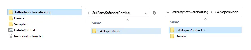
Figure 1: Project directory structure
Next, create a Demos folder inside the CANopenNode directory to create example projects following the LibSamples structure. The files CO_OD.c and CO_OD.h, which contain the Object Dictionary, should be copied to the Demos/CANopen_Basic folder. The original main.c file should be replaced with the one from the CANopenNode example.
Copy the files CO_driver.c and CO_driver_target.h from the CANopenNode-1.3/stack/drvTemplate folder into the example project directory.
Create an MDK-ARM project in the CANopen_Basic folder, referencing the LibSample project structure, and add the necessary compiler paths. After porting, the CANopen_Basic example structure should look like Figure 2:
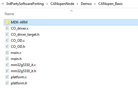
Figure 2: Final project structure
Since this is a bare-metal port, the mainline thread is placed inwhile(1), the CAN reception thread is in the FlexCAN interrupt service routine, and the timer thread is in a 1ms timer interrupt service routine, following the CANopenNode design.
Timer Configuration in main.c
This code initializes and configures timer TIM1 and implements its corresponding interrupt handler.
/* Setup the timer. */
void app_tim_init(void)
{
    NVIC_InitTypeDef        NVIC_InitStruct;
    TIM_TimeBaseInitTypeDef TIM_TimeBaseInitStruct;
    RCC_ClocksTypeDef RCC_Clocks;
    RCC_GetClocksFreq(&RCC_Clocks);
    RCC_APB2PeriphClockCmd(RCC_APB2ENR_TIM1, ENABLE);
    TIM_TimeBaseStructInit(&TIM_TimeBaseInitStruct);
    TIM_TimeBaseInitStruct.TIM_Prescaler         = (RCC_Clocks.PCLK2_Frequency / APP_TIM_UPDATE_STEP - 1);
    TIM_TimeBaseInitStruct.TIM_CounterMode       = TIM_COUNTERMODE_UP;
    TIM_TimeBaseInitStruct.TIM_Period            = (APP_TIM_UPDATE_PERIOD - 1);
    TIM_TimeBaseInitStruct.TIM_ClockDivision     = TIM_CKD_DIV1;
    TIM_TimeBaseInitStruct.TIM_RepetitionCounter = 0;
    TIM_TimeBaseInit(TIM1, &TIM_TimeBaseInitStruct);
    TIM_ClearFlag(TIM1, TIM_IT_UPDATE);
    TIM_ITConfig(TIM1, TIM_IT_UPDATE, ENABLE);
    NVIC_InitStruct.NVIC_IRQChannel                   = TIM1_UP_IRQn;
    NVIC_InitStruct.NVIC_IRQChannelPreemptionPriority = 0;
    NVIC_InitStruct.NVIC_IRQChannelSubPriority        = 0;
    NVIC_InitStruct.NVIC_IRQChannelCmd                = ENABLE;
    NVIC_Init(&NVIC_InitStruct);
}
void TIM1_UP_IRQHandler(void)
{
    TIM_ClearITPendingBit(TIM1, TIM_IT_UPDATE);
    tmrTask_thread();
}
Timer Thread Task Implementation in main.c
Here, the tmrTask_thread() function is completed.
/* timer thread executes in constant intervals ********************************/
void tmrTask_thread(void){
    INCREMENT_1MS(CO_timer1ms);
    if (CO->CANmodule[0]->CANnormal) {
        bool_t syncWas;
        /* Process Sync */
        syncWas = CO_process_SYNC(CO, TMR_TASK_INTERVAL);
        /* Read inputs */
        CO_process_RPDO(CO, syncWas);
        /* Further I/O or nonblocking application code may go here. */
        /* Write outputs */
        CO_process_TPDO(CO, syncWas, TMR_TASK_INTERVAL);
        /* verify timer overflow */
        if((TIM_GetITStatus(TIM1, TIM_IT_UPDATE) & TIM_IT_UPDATE) != 0u) {
            CO_errorReport(CO->em, CO_EM_ISR_TIMER_OVERFLOW, CO_EMC_SOFTWARE_INTERNAL, 0u);
            TIM_ClearITPendingBit(TIM1, TIM_IT_UPDATE);
        }
    }
}
FlexCAN Interrupt Service Routine in main.c
/* CAN interrupt function *****************************************************/
void FLEXCAN_IRQHandler(void)
{
    FLEXCAN_TransferHandleIRQ(FLEXCAN, &FlexCAN_Handle);
    CO_CANinterrupt(CO->CANmodule[0]);
    __DSB();
}
FlexCAN Module Configuration in CO_driver.c
This includes configuration for FlexCAN-related GPIO pins, clock, and CAN message receive/transmit buffers.
void FlexCAN_Configure(uint32_t can_bitrate)
{
    GPIO_InitTypeDef GPIO_InitStruct;
    NVIC_InitTypeDef NVIC_InitStruct;
    RCC_ClocksTypeDef RCC_Clocks;
    flexcan_config_t       FlexCAN_ConfigStruct;
    flexcan_rx_mb_config_t FlexCAN_RxMB_ConfigStruct;
    RCC_GetClocksFreq(&RCC_Clocks);
    RCC_APB1PeriphClockCmd(RCC_APB1PERIPH_FLEXCAN, ENABLE);
    RCC_AHBPeriphClockCmd(RCC_AHBENR_GPIOA, ENABLE);
    GPIO_PinAFConfig(GPIOA, GPIO_PINSOURCE11, GPIO_AF_9);
    GPIO_PinAFConfig(GPIOA, GPIO_PINSOURCE12, GPIO_AF_9);
    GPIO_StructInit(&GPIO_InitStruct);
    GPIO_InitStruct.GPIO_Pin   = GPIO_PIN_11;
    GPIO_InitStruct.GPIO_Speed = GPIO_SPEED_HIGH;
    GPIO_InitStruct.GPIO_Mode  = GPIO_MODE_FLOATING;
    GPIO_Init(GPIOA, &GPIO_InitStruct);
    GPIO_StructInit(&GPIO_InitStruct);
    GPIO_InitStruct.GPIO_Pin   = GPIO_PIN_12;
    GPIO_InitStruct.GPIO_Speed = GPIO_SPEED_HIGH;
    GPIO_InitStruct.GPIO_Mode  = GPIO_MODE_AF_PP;
    GPIO_Init(GPIOA, &GPIO_InitStruct);
    NVIC_InitStruct.NVIC_IRQChannel                   = FLEXCAN_IRQn;
    NVIC_InitStruct.NVIC_IRQChannelPreemptionPriority = 0;
    NVIC_InitStruct.NVIC_IRQChannelSubPriority        = 0;
    NVIC_InitStruct.NVIC_IRQChannelCmd                = ENABLE;
    NVIC_Init(&NVIC_InitStruct);
    FLEXCAN_GetDefaultConfig(&FlexCAN_ConfigStruct);
    FlexCAN_ConfigStruct.baudRate             = can_bitrate*1000;
    FlexCAN_ConfigStruct.clkSrc               = Enum_Flexcan_ClkSrc1;
    FlexCAN_ConfigStruct.enableLoopBack       = false;
    FlexCAN_ConfigStruct.disableSelfReception = true;
    FlexCAN_ConfigStruct.enableIndividMask    = true;
    #if 1    /* Baudrate calculate by automatically */
    FLEXCAN_CalculateImprovedTimingValues(FlexCAN_ConfigStruct.baudRate, RCC_Clocks.PCLK1_Frequency, &FlexCAN_ConfigStruct.timingConfig);
#else  /* You can modify the parameters yourself */
    FlexCAN_ConfigStruct.timingConfig.preDivider = 23;
    FlexCAN_ConfigStruct.timingConfig.propSeg    = 6;
    FlexCAN_ConfigStruct.timingConfig.phaseSeg1  = 3;
    FlexCAN_ConfigStruct.timingConfig.phaseSeg2  = 3;
    FlexCAN_ConfigStruct.timingConfig.rJumpwidth = 3;
#endif
    FLEXCAN_Init(FLEXCAN, &FlexCAN_ConfigStruct);
    /* Set Tx MB_2. */
    FLEXCAN_TxMbConfig(FLEXCAN, BOARD_FLEXCAN_TX_MB_CH, ENABLE);
    FLEXCAN_TransferCreateHandle(FLEXCAN, &FlexCAN_Handle, FlexCAN_Transfer_Callback, NULL);
    /* Set Rx MB_0. */
    FlexCAN_RxMB_ConfigStruct.id     = FLEXCAN_ID_STD(0x222);
    FlexCAN_RxMB_ConfigStruct.format = Enum_Flexcan_FrameFormatStandard;
    FlexCAN_RxMB_ConfigStruct.type   = Enum_Flexcan_FrameTypeData;
    FLEXCAN_RxMbConfig(FLEXCAN, BOARD_FLEXCAN_RX_MB_CH, &FlexCAN_RxMB_ConfigStruct, ENABLE);
    /* Set Rx Individual Mask. */
    FLEXCAN_SetRxIndividualMask(FLEXCAN, BOARD_FLEXCAN_RX_MB_CH, FLEXCAN_RX_MB_STD_MASK(0x000, 0, 0));
    FlexCAN_MB0_FrameStruct.length = (uint8_t)(8);
    FlexCAN_MB0_FrameStruct.type   = (uint8_t)Enum_Flexcan_FrameTypeData;
    FlexCAN_MB0_FrameStruct.format = (uint8_t)Enum_Flexcan_FrameFormatStandard;
    FlexCAN_MB0_FrameStruct.id     = FLEXCAN_ID_STD(0x222);
    FlexCAN_MB0_TransferStruct.mbIdx = BOARD_FLEXCAN_RX_MB_CH;
    FlexCAN_MB0_TransferStruct.frame = &FlexCAN_MB0_FrameStruct;
    FLEXCAN_TransferReceiveNonBlocking(FLEXCAN, &FlexCAN_Handle, &FlexCAN_MB0_TransferStruct);
}
Conclusion
This article has outlined the basic concepts of the CANopen protocol and detailed the process of porting the CANopenNode stack to the MM32G5330 MCU using its FlexCAN peripheral. Board-level validation confirms that the ported stack functions correctly, providing a foundation for further device integration and communication. Developers can apply this method to other MindMotion MCUs with FlexCAN to implement reliable CANopen communication for their specific application needs.