ALLPCB


Before an application can be loaded via methods like a USB drive or an Over-the-Air (OTA) update, a BootLoader program must be present. This article explores several common methods for partitioning Flash memory to accommodate OTA firmware updates.
Standalone Partition
The standalone method reserves a dedicated section of Flash memory for the BootLoader. As shown in the diagram, there are three distinct areas:
BootLoader: The program that manages firmware updates.
Firmware A: The active application partition.
Firmware B: The backup partition for storing new firmware downloads.
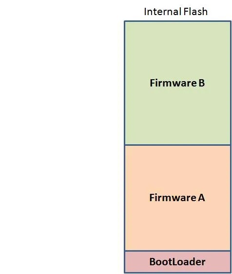
The BootLoader stores the newly received firmware in the Firmware B partition. After successful validation, the BootLoader erases the contents of Firmware A and copies the new firmware from Firmware B into Firmware A. This is a common and reliable approach because the backup partition enhances update safety.
Embedded Partition
In the embedded method, the BootLoader is integrated within the application firmware itself.
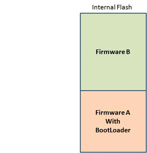
When a new firmware image is received and stored in the Firmware B partition, the BootLoader validates it. If validation is successful, program execution transfers directly to the new application in Firmware B.
External Memory Method
The external memory method is suitable for MCUs with limited internal Flash. An external storage chip is used to cache the new firmware image.
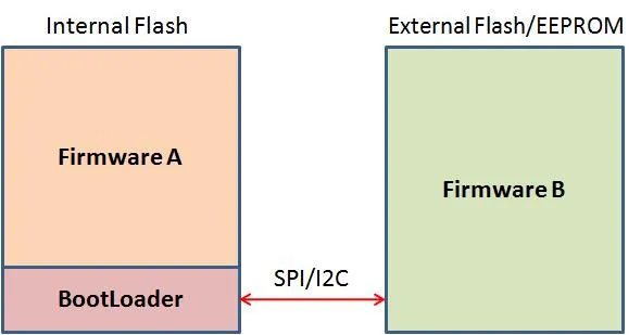
The BootLoader stores the incoming firmware on this external chip. After successful validation, it erases the application in the internal Flash (Firmware A) and copies the new firmware from the external memory to Firmware A.
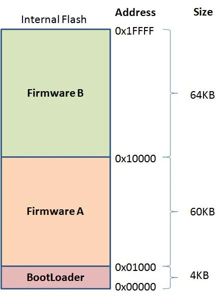
MCU Flash space cannot be partitioned arbitrarily. The internal Flash memory is erased in minimal units called pages or blocks. Consequently, partition boundaries must align with the actual page or block sizes of the target MCU. For example, let's consider a standalone partition scheme for the TMPM3H6FWFG. Its datasheet indicates 128 KB of internal Flash, with a minimum page erase size of 4 KB and a block erase size of 32 KB.
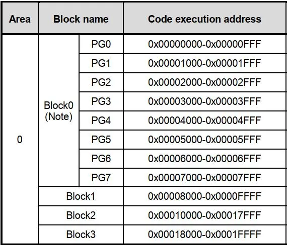
Based on this information, the MCU's internal Flash could be partitioned as follows:
This article provides a brief overview of MCU Flash partitioning for OTA updates. The most suitable method for a specific project depends on its unique requirements and must be evaluated accordingly.