ALLPCB


Introduction
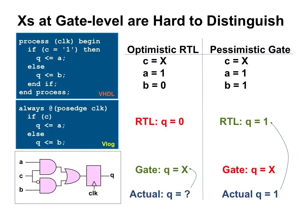
In real silicon, register initial values are either 1 or 0. However, during RTL simulation, propagation of X state often causes problems. For example, a signal expected to be 0 may instead appear as X in simulation.
1. X-State Propagation Example
In the following example:
The input mty_in[3:0] indicates the number of invalid bytes in data_in[127:0]. For instance, when the last beat mty_in[3:0] is 4'd2, data_in[15:0] are invalid. Because the input data comes from another module, data_in[15:0] might be X. The 128-bit data_in is then written into ram_wrapper. ram_wrapper contains logic that computes parity_err_int whose input is wr_data[127:0], i.e., the source is the 128-bit data_in. If any bit of data_in[127:0] is X, parity_err_int will evaluate to X, and this will propagate through the interrupt module to the CSR register module. Note: in real silicon, this bug does not exist.
This is just one small example; there are many similar scenarios. X-state propagation creates significant difficulties for RTL simulation. One mitigation is to isolate X states at the module interface so internal signals remain stable.
2. X-State Isolation Implementation
The intended isolation behavior is as follows: when mty_in is nonzero on the last beat, input data_in may contain invalid bytes that are X. After simple processing, the internal signal data_in_d1 has all bits in stable values, with invalid bytes assigned 0.
Core processing logic: when data_exit_invld_bits is 1, it indicates the last beat and that data_in contains invalid bytes. In that case, assign data_in_d1_nxt to data_in_d1.
`timescale 1ns/1ps
module x_state_handle_top ( ) ;