ALLPCB


Creating a weather station PCB that delivers precise sensor readings is a challenging yet rewarding task for engineers and hobbyists alike. Whether you're designing for personal use or a commercial product, sensor accuracy is critical. So, how do you optimize a weather station PCB for the best results? The key lies in mastering thermal management, strategic sensor placement, minimizing heat interference, and selecting the right materials. In this comprehensive guide, we'll uncover the design secrets to help you achieve unparalleled accuracy in your weather station PCB projects, focusing on practical tips for weather station PCB thermal management, sensor placement guidelines, minimizing heat interference on PCB, and PCB material selection for accurate readings.
Why Sensor Accuracy Matters in Weather Station PCBs
Weather stations rely on sensors to measure environmental factors like temperature, humidity, pressure, and wind speed. Even small inaccuracies in these readings can lead to unreliable data, affecting everything from personal weather predictions to critical agricultural or industrial applications. A well-designed PCB ensures that sensors operate in optimal conditions, free from interference caused by heat, electrical noise, or poor material choices. Let’s dive into the core aspects of PCB design that directly impact sensor accuracy and how you can address them effectively.
Mastering Weather Station PCB Thermal Management
Heat is one of the biggest enemies of sensor accuracy in weather station designs. Components on a PCB, such as microcontrollers or power regulators, generate heat during operation. If not managed properly, this heat can interfere with temperature and humidity sensors, leading to skewed readings. Effective weather station PCB thermal management is essential to maintain a stable environment for your sensors.
1. Use Heat Sinks and Thermal Vias
Heat sinks are a simple yet effective way to dissipate heat from high-power components. Place heat sinks near components like voltage regulators that tend to get hot. Additionally, incorporate thermal vias—small holes filled with conductive material—in your PCB design. These vias help transfer heat from the top layer to the bottom layer or to a dedicated ground plane, reducing the thermal load near sensitive sensors. For instance, a thermal via array under a power IC can reduce local temperatures by up to 10-15°C, depending on the design and airflow.
2. Optimize Component Layout for Heat Distribution
Position heat-generating components away from temperature-sensitive sensors. For example, keep power transistors or high-current traces at least 10-15 mm away from temperature sensors to avoid direct heat transfer. You can also use copper pours as heat spreaders on the PCB surface to distribute heat evenly and prevent hotspots. Ensure that these copper areas are connected to ground planes for better heat dissipation.
3. Incorporate Active Cooling if Necessary
For weather stations operating in high-temperature environments or with dense component layouts, consider active cooling solutions like small fans. While this adds complexity, it can maintain PCB temperatures below 40°C, a threshold often critical for accurate sensor performance. If active cooling isn’t feasible, ensure adequate ventilation in the enclosure design to allow natural airflow.
Sensor Placement Guidelines for Maximum Accuracy
Where you place sensors on your weather station PCB can make or break the accuracy of your readings. Poor placement can expose sensors to interference from heat, electromagnetic noise, or physical obstructions. Follow these sensor placement guidelines to ensure reliable data collection.
1. Isolate Sensors from Heat Sources
As mentioned earlier, keep sensors like thermistors or humidity sensors far from heat-generating components. If space constraints make this difficult, consider using thermal barriers such as insulating materials or cutouts in the PCB to reduce heat conduction. For instance, a small slot around a temperature sensor can minimize heat transfer from nearby traces, improving accuracy by up to 1-2°C in some cases.
2. Position Sensors for Environmental Exposure
Sensors need to interact with the environment to provide accurate readings. Place temperature and humidity sensors near the edge of the PCB or in areas exposed to ambient air. Avoid burying them under other components or inside tightly packed enclosures. For outdoor weather stations, consider mounting sensors on a separate daughterboard that can be positioned outside the main enclosure for direct exposure to weather conditions.
3. Minimize Electromagnetic Interference (EMI)
High-frequency components or switching regulators can introduce EMI, which affects sensor output. Place sensitive analog sensors away from digital traces and high-speed signal lines. Use ground planes or shielding to isolate sensors from EMI. For example, a ground plane beneath a pressure sensor can reduce noise pickup, ensuring cleaner data with variations as low as 0.1 hPa.
Minimizing Heat Interference on PCB Designs
Beyond thermal management and sensor placement, specific design techniques can further help in minimizing heat interference on PCB layouts. Heat interference often manifests as localized temperature spikes that distort sensor readings, especially in compact designs where components are closely packed.
1. Use Low-Power Components
Opt for low-power microcontrollers and regulators to reduce overall heat generation. For example, choosing a microcontroller with a quiescent current below 1 mA can significantly lower the thermal footprint compared to older, power-hungry models. Check datasheets for power dissipation ratings and select components that balance performance with minimal heat output.
2. Implement Power Planes Strategically
Power planes can act as unintended heat spreaders if not designed carefully. Split power planes to isolate high-current sections from sensor areas. This prevents heat from traveling through the plane to sensitive regions. Additionally, keep power traces short and wide to minimize resistive heating, which can contribute to temperature rises of 5-10°C in poorly designed layouts.
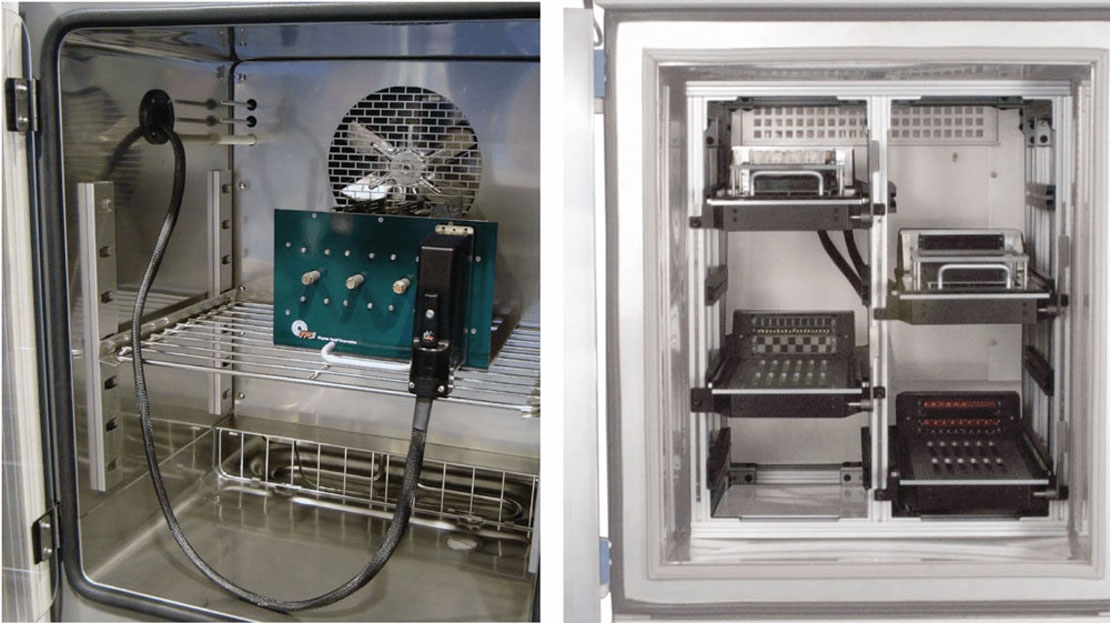
3. Test and Simulate Thermal Performance
Before finalizing your design, use thermal simulation tools to identify potential hotspots. Software can predict temperature distribution across the PCB, allowing you to adjust layouts proactively. For instance, simulations might reveal that a specific trace routing increases temperatures near a sensor by 8°C, prompting a redesign to avoid this issue. Post-assembly, use infrared cameras to validate thermal performance under real-world conditions.
PCB Material Selection for Accurate Readings
The materials used in your PCB play a significant role in sensor accuracy. Poor material choices can lead to thermal expansion, signal degradation, or heat retention, all of which impact performance. Let’s explore PCB material selection for accurate readings to ensure your weather station delivers reliable data.
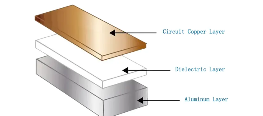
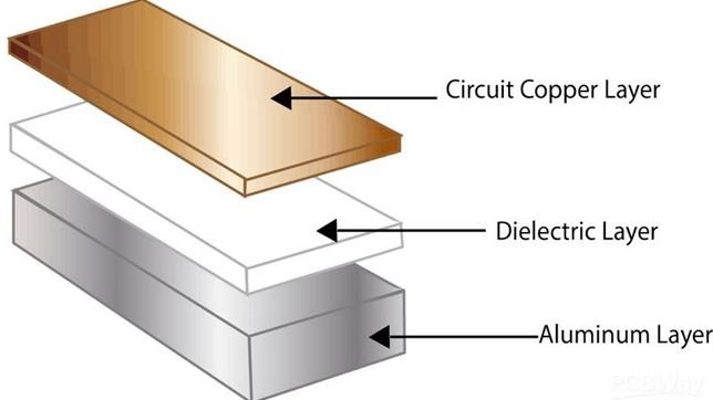
1. Choose Materials with Low Thermal Conductivity for Sensor Areas
Standard FR-4 material is widely used for PCBs due to its cost-effectiveness and durability. However, it has moderate thermal conductivity, which can transfer heat to sensors. For high-accuracy designs, consider hybrid boards where sensor areas use materials like polyimide with lower thermal conductivity (around 0.12 W/m·K compared to FR-4’s 0.25 W/m·K). This helps isolate sensors from board-wide temperature fluctuations.
2. Opt for Stable Dielectric Properties
Humidity and pressure sensors often rely on precise capacitance or resistance measurements. Materials with unstable dielectric constants can introduce errors in these readings, especially under varying environmental conditions. Select PCB substrates with low dielectric loss and high stability across temperature ranges (e.g., Rogers materials for critical applications). This ensures signal integrity, reducing errors in humidity readings by up to 2-3% in humid environments.
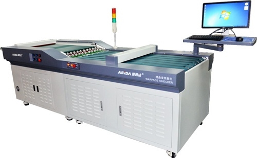
3. Consider Thermal Expansion Coefficients
Thermal expansion can cause mechanical stress on sensors, leading to drift in readings over time. Match the coefficient of thermal expansion (CTE) of the PCB material to that of the sensor packages. For example, a CTE mismatch of more than 5 ppm/°C between the board and sensor can induce stress, shifting temperature readings by 0.5°C or more over a 50°C temperature swing. FR-4 typically has a CTE of 14-17 ppm/°C, so verify compatibility with your sensor specifications.
Additional Tips for Weather Station PCB Optimization
Beyond the core design aspects, a few additional practices can elevate the performance of your weather station PCB:
- Calibration: Regularly calibrate sensors post-assembly to account for any manufacturing variances or environmental impacts. A temperature sensor might show a deviation of 0.3°C out of the box, which calibration can correct.
- Enclosure Design: Use enclosures with proper ventilation or radiation shields to protect sensors from direct sunlight or rain while allowing air circulation. This can prevent temperature errors of up to 5°C on sunny days.
- Signal Conditioning: Incorporate filters or amplifiers near sensors to clean up signals before they reach the microcontroller. A low-pass filter can reduce noise in humidity readings, improving accuracy by 1-2%.
Conclusion: Building a High-Accuracy Weather Station PCB
Designing a weather station PCB for optimal sensor accuracy requires careful attention to detail in several key areas. By focusing on weather station PCB thermal management, following sensor placement guidelines, minimizing heat interference on PCB, and prioritizing PCB material selection for accurate readings, you can create a reliable and precise weather monitoring system. Start with a well-thought-out layout, use simulation tools to predict performance, and select materials that support your design goals. With these design secrets, your weather station will deliver data you can trust, whether for personal projects or professional applications.
Implement these strategies in your next project, and watch as your sensor accuracy reaches new heights. Remember, a small investment in design optimization can yield significant improvements in performance and reliability over the long term.