ALLPCB


In the world of PCB design, achieving optimal signal integrity is a critical goal for engineers. One of the key factors influencing this is PCB trace spacing. But what exactly is trace spacing, and how does it impact performance? Simply put, trace spacing refers to the distance between conductive paths on a printed circuit board (PCB). Proper spacing ensures signals travel without interference, prevents crosstalk, and maintains impedance control for high-speed designs. In this comprehensive guide, we’ll dive deep into signal integrity rules, explore trace width and spacing best practices, and uncover strategies for crosstalk prevention and impedance control to help you design high-performing PCBs.
What Is PCB Trace Spacing and Why Does It Matter?
PCB trace spacing is the physical distance between two or more conductive traces on a circuit board. This spacing isn’t just about fitting components on a board—it directly affects how signals behave during transmission. If traces are too close, you risk interference or crosstalk, where signals from one trace “leak” into another, causing errors. If traces are too far apart, you might waste valuable board space or struggle with impedance mismatches in high-speed designs.
Signal integrity, the quality and reliability of electrical signals as they travel through a PCB, hinges on proper trace spacing. Poor spacing can lead to issues like electromagnetic interference (EMI), signal delays, or even complete circuit failure. For modern electronics, where speeds often exceed 1 GHz, mastering trace spacing is non-negotiable. Whether you're designing for consumer gadgets or industrial systems, understanding and applying signal integrity rules through trace spacing can make or break your project.
The Basics of Trace Width and Spacing for Signal Integrity
Before diving into advanced concepts, let’s cover the fundamentals of trace width and spacing. Trace width refers to the thickness of the conductive path, while spacing is the gap between paths. Both parameters are critical for maintaining signal integrity, especially in high-speed designs.
- Trace Width: Wider traces can handle more current and reduce resistance, but they take up more space. For high-speed signals, width also affects impedance, which must be controlled to match the circuit’s requirements (often 50 ohms for single-ended signals or 100 ohms for differential pairs).
- Trace Spacing: The gap between traces prevents electrical interference. For low-voltage designs, a spacing of 6 mils (0.006 inches) might suffice, but high-voltage or high-speed applications often require 10 mils or more to avoid crosstalk and arcing.
Balancing these two factors depends on your design’s specific needs, including signal speed, voltage levels, and board density. For instance, a typical USB 2.0 signal running at 480 Mbps might require a trace width of 8 mils and spacing of 8 mils to maintain signal integrity, while a PCIe 4.0 signal at 16 Gbps could demand tighter control with differential pair spacing of 5 mils or less.
Signal Integrity Rules: Key Guidelines for PCB Design
To ensure your PCB performs reliably, follow these essential signal integrity rules related to trace spacing and layout:
- Maintain Consistent Impedance: Impedance mismatches cause signal reflections, leading to data errors. Use trace width calculators or simulation tools to match impedance to your design’s target value, often 50 ohms for RF signals. Spacing impacts this too—closer traces increase capacitance, lowering impedance.
- Minimize Trace Lengths: Longer traces introduce delays and increase the risk of interference. Keep high-speed signal paths as short as possible.
- Avoid Sharp Corners: Sharp bends in traces (like 90-degree turns) can cause signal reflections. Use 45-degree angles or curved traces instead.
- Separate High-Speed and Low-Speed Signals: Keep high-speed traces away from low-speed or power traces to reduce noise coupling. A good rule of thumb is to maintain a spacing of at least 3 times the trace width (3W rule) for critical signals.
- Use Ground Planes: A solid ground plane beneath signal traces provides a return path for currents, reducing EMI and improving signal stability.
By adhering to these rules, you lay a strong foundation for a PCB design that performs consistently, even under demanding conditions.
Crosstalk Prevention: How Trace Spacing Plays a Role
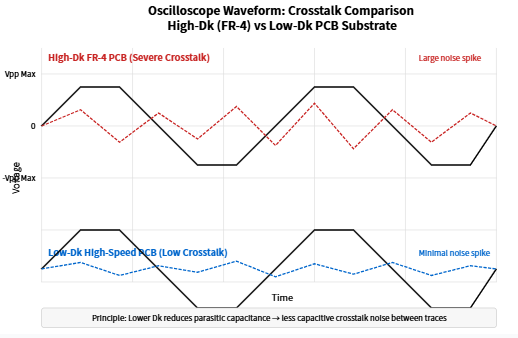
Crosstalk occurs when a signal from one trace interferes with a neighboring trace, often due to electromagnetic coupling. This is a major concern in high-speed designs, where even small interference can corrupt data. The primary way to achieve crosstalk prevention is through proper trace spacing.
The “3W rule” is a widely accepted guideline for minimizing crosstalk. It states that the spacing between two traces should be at least three times the width of the traces. For example, if your trace width is 5 mils, the spacing should be at least 15 mils. This distance reduces the capacitive and inductive coupling between traces, lowering the risk of interference.
For differential pairs (common in high-speed protocols like USB or HDMI), spacing between the pair’s traces should be tight (often 5-8 mils) to maintain coupling within the pair, while spacing to other traces should follow the 3W rule or greater. Additionally, routing high-speed traces on different layers or using guard traces (grounded traces between signal traces) can further isolate signals and prevent crosstalk.
Impedance Control: Fine-Tuning Trace Spacing and Width
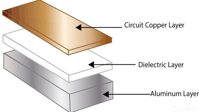
Impedance control is a cornerstone of high-speed PCB design, ensuring that signals travel without reflections or distortions. Impedance depends on several factors, including trace width, spacing, dielectric material, and layer stackup. Let’s focus on how trace spacing and width influence this critical parameter.
For a single-ended trace, impedance is calculated using the formula for microstrip or stripline configurations. A typical target is 50 ohms, which might require a trace width of 10 mils and spacing to ground planes or adjacent traces carefully adjusted based on the board’s dielectric constant (often around 4.2 for FR-4 material). Closer spacing to a ground plane reduces impedance due to increased capacitance, while wider spacing increases it.
In differential pairs, impedance is often 100 ohms, and spacing between the two traces in the pair must be tightly controlled. For instance, a 5-mil trace width with a 5-mil spacing between traces in the pair might achieve the desired impedance on a standard 4-layer board. However, spacing to other traces or planes must still follow guidelines like the 3W rule to avoid interference.
To achieve precise impedance control, use PCB design software with built-in calculators or collaborate with your manufacturing partner to verify stackup and material properties. Small deviations in spacing or width during fabrication can throw off impedance, so always account for manufacturing tolerances (typically ±10%).
Best Practices for High-Speed PCB Design
Designing for high-speed signals (above 100 MHz) demands extra attention to trace spacing and layout. Here are actionable tips to optimize performance:
- Use Differential Routing: For protocols like PCIe or USB 3.0, route differential pairs with equal lengths and tight spacing within the pair (e.g., 5 mils) to ensure signal synchronization.
- Layer Stackup Planning: Place high-speed traces on inner layers if possible, sandwiched between ground planes, to shield them from external noise. A 6-layer stackup with signal-ground-signal-ground-power-signal configuration works well for many designs.
- Control Dielectric Thickness: The distance between a trace and its reference plane affects impedance. A thinner dielectric (e.g., 4 mils) lowers impedance, while a thicker one (e.g., 10 mils) increases it. Specify this in your design files.
- Avoid Vias in High-Speed Paths: Vias introduce inductance and capacitance, disrupting signal integrity. If unavoidable, use back-drilling to remove unused via stubs.
These practices, combined with proper PCB trace spacing, can significantly enhance your board’s performance, especially for applications like 5G, IoT, or automotive electronics.
Common Mistakes to Avoid with Trace Spacing
Even experienced designers can make errors when it comes to trace spacing. Here are some pitfalls to watch out for:
- Ignoring Manufacturing Limits: If spacing is too tight (below 3 mils for standard processes), fabrication errors can lead to shorts. Always check your manufacturer’s capabilities—most support 6-mil spacing as a minimum for cost-effective production.
- Overlooking High-Voltage Spacing: For power traces carrying high voltages (above 100V), spacing must comply with safety standards like IPC-2221, often requiring 30 mils or more to prevent arcing.
- Neglecting Crosstalk in Dense Designs: In compact boards, squeezing traces too close violates the 3W rule, leading to interference. Plan your layout early to allocate enough space.
- Inconsistent Impedance: Failing to adjust spacing when changing trace width can disrupt impedance, especially in RF or high-speed digital circuits.
By staying mindful of these issues, you can avoid costly redesigns and ensure your PCB meets performance expectations.
Tools and Resources for Mastering Trace Spacing
Designing with proper trace spacing doesn’t have to be a guessing game. Several tools can help you achieve precision:
- PCB Design Software: Use tools with built-in impedance calculators and spacing rule checks to validate your layout before manufacturing.
- Online Calculators: Free resources can estimate impedance based on trace width, spacing, and material properties. These are great for quick checks during early design stages.
- Simulation Tools: For high-speed designs, simulate signal behavior to identify potential crosstalk or impedance issues before prototyping.
- Manufacturer Guidelines: Work closely with your PCB fabrication partner to understand their spacing and width tolerances, ensuring your design is manufacturable.
These resources empower you to fine-tune trace width and spacing, ensuring signal integrity across diverse applications.
Conclusion: Elevate Your PCB Design with Proper Trace Spacing
Mastering PCB trace spacing is a game-changer for achieving optimal signal integrity in your designs. By understanding the interplay between trace width and spacing, applying signal integrity rules, prioritizing crosstalk prevention, and maintaining strict impedance control, you can create PCBs that perform reliably even in the most demanding applications. From following the 3W rule to leveraging design tools and manufacturer expertise, every step you take toward precise spacing brings you closer to a flawless design.
Whether you’re working on a simple prototype or a complex high-speed board, remember that trace spacing isn’t just a detail—it’s a fundamental aspect of quality PCB design. Apply these principles in your next project, and watch your circuit performance soar.