 ALLPCB


If you're working on small-scale electronics projects and searching for affordable PCB testing methods, you're in the right place. Testing printed circuit boards (PCBs) doesn't have to break the bank, even for hobbyists or small teams with limited budgets. In this comprehensive guide, we'll explore DIY PCB testing, low-cost PCB inspection techniques, and simple PCB test methods tailored for PCB testing for hobbyists. Whether you're building a prototype at home or running a small workshop, these strategies will help ensure your boards work as intended without expensive equipment.
Below, we'll dive into practical tips, step-by-step processes, and tools you can use to test your PCBs effectively while keeping costs low. Let’s get started on making your projects successful with budget-friendly solutions.
Why PCB Testing Matters for Small-Scale Projects
Before we explore testing strategies, let’s understand why testing is crucial, even for small projects. A single fault in a PCB—whether it’s a short circuit, an open connection, or a misplaced component—can render your entire project useless. For hobbyists and small-scale developers, replacing faulty boards or components can quickly add up in terms of time and money.
Testing ensures that your PCB functions as designed, saving you from costly mistakes down the line. It also helps build confidence in your prototypes before moving to larger production runs. With affordable PCB testing methods, you can catch issues early without investing in professional-grade equipment.
Essential Tools for Low-Cost PCB Inspection
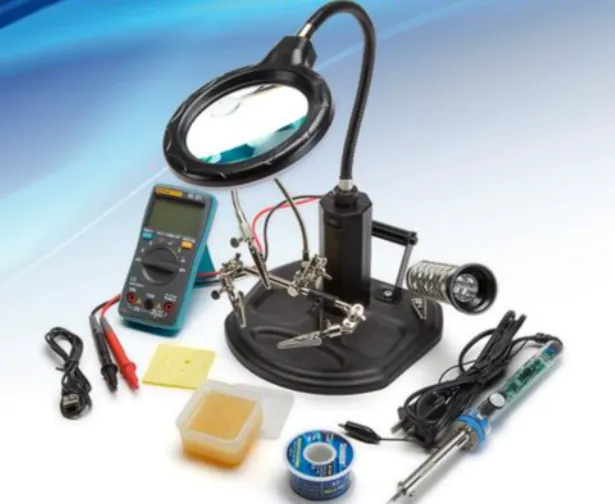
One of the first steps in low-cost PCB inspection is gathering the right tools. You don’t need expensive machinery to get started. Here are some budget-friendly tools that can help with PCB testing for hobbyists:
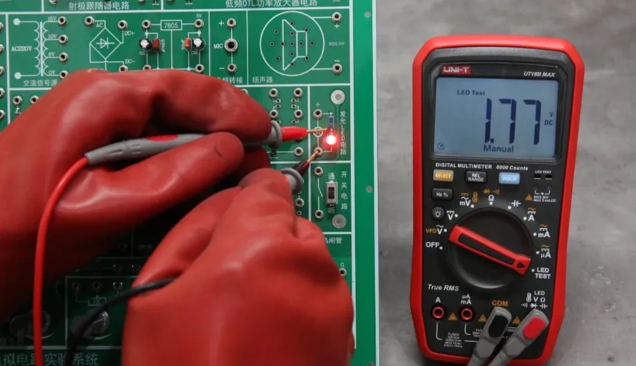
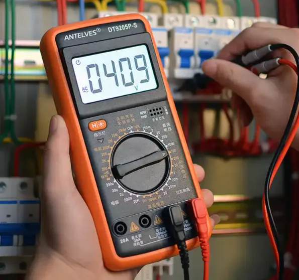
- Multimeter: A basic digital multimeter (often under $20) can measure voltage, current, and resistance. Use it to check for continuity, shorts, and open circuits on your PCB. For example, a typical multimeter can detect if a trace has a resistance higher than expected, like over 1 ohm, which might indicate a break.
- Magnifying Glass or Loupe: Visual inspection is key for spotting soldering defects or misaligned components. A magnifying tool costing less than $10 can help you see tiny details on your board.
- Power Supply: A simple adjustable DC power supply (around $30-$50) lets you power your PCB safely during testing. Look for one with a current limit to avoid damaging components if there’s a short.
- Test Probes and Clips: These inexpensive accessories (often under $5 for a set) make it easier to connect your multimeter to specific points on the PCB without risking accidental shorts.
With these tools, you can perform a wide range of tests at home or in a small workshop. They’re the foundation of DIY PCB testing and are accessible to anyone on a tight budget.
Simple PCB Test Methods for Hobbyists
Now that you have the tools, let’s look at some simple PCB test methods you can apply. These approaches are practical for small-scale projects and don’t require advanced skills or costly setups.
1. Visual Inspection for Obvious Defects
Start with a thorough visual check. Look for issues like solder bridges (where solder connects two points that shouldn’t be connected), cold solder joints (dull or cracked solder), or misaligned components. Use a magnifying glass to inspect small pads and traces. This step is completely free and can catch up to 50% of common PCB issues before you even power up the board.
2. Continuity Testing with a Multimeter
Continuity testing is a core part of affordable PCB testing. Set your multimeter to the continuity mode (often indicated by a diode symbol or a beep sound). Touch the probes to two points that should be connected, like a trace or a pad. If you hear a beep, the connection is good. If there’s no sound, you’ve found an open circuit that needs fixing.
For example, if a trace between a microcontroller pin and a resistor shows no continuity, there might be a break in the trace. This test is quick and helps identify manufacturing defects or assembly errors.
3. Power-On Testing with Caution
Once you’ve confirmed there are no obvious shorts or opens, power up the PCB using a current-limited power supply. Start with a low voltage (e.g., 3.3V or 5V, depending on your circuit) and monitor for unusual behavior like excessive heat or smoke. Measure key points with your multimeter to ensure voltages are within expected ranges, such as 5V ± 0.2V at a regulator output.
Tip: Always double-check polarity before applying power to avoid damaging components. This step is critical in DIY PCB testing to ensure basic functionality.
DIY PCB Testing Setups for Greater Efficiency
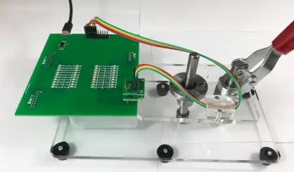
For hobbyists working on multiple projects, setting up a dedicated DIY PCB testing station can save time and improve accuracy. Here’s how to build a basic setup without spending much:
- Test Jig: Create a simple test jig using a piece of wood or plastic to hold your PCB in place during testing. Add spring-loaded test pins (pogo pins, available for under $1 each) to make repeatable connections to test points. This is especially useful if you’re testing multiple copies of the same board.
- Organized Workspace: Keep your tools and components organized on a small desk or workbench. Use labeled containers for resistors, capacitors, and other parts to avoid mix-ups during assembly and testing.
- Basic Automation with Microcontrollers: If you’re comfortable with programming, use a low-cost microcontroller board (around $5-$10) to automate simple tests. For instance, write a script to check if specific pins output the expected voltage (e.g., 3.3V) and display results on a small screen or serial monitor.
This setup enhances your ability to perform low-cost PCB inspection efficiently, especially for recurring projects. It’s a step up from manual testing while remaining budget-friendly.
Common PCB Issues and How to Test for Them
Understanding common PCB problems can guide your testing efforts. Here are a few issues often encountered in small-scale projects and how to detect them using simple PCB test methods:
- Short Circuits: These occur when two traces or pads are unintentionally connected, often due to excess solder. Use a multimeter in continuity mode to test between adjacent traces. If there’s a beep where there shouldn’t be, you’ve found a short. Typical resistance in a short might read as low as 0.1 ohms.
- Open Circuits: These are breaks in connections, preventing current flow. Again, use continuity mode to check traces and solder joints. No beep means an open circuit that needs repair, such as resoldering a joint or replacing a damaged trace.
- Component Failures: A faulty component, like a capacitor or IC, can cause the entire circuit to malfunction. Test components individually if possible—measure a capacitor’s value with a multimeter (if it supports capacitance mode) or check an IC’s output signals against its datasheet specifications.
By focusing on these issues during PCB testing for hobbyists, you can pinpoint problems quickly and avoid wasting time on trial-and-error fixes.
Advanced Yet Affordable PCB Testing Techniques
If you’re ready to take your testing to the next level without breaking the bank, consider these slightly more advanced but still affordable PCB testing methods:
1. In-Circuit Testing with a DIY Setup
In-circuit testing involves checking components while they’re soldered onto the PCB. Use a multimeter to measure voltages and resistances at key points. For example, if a resistor in a voltage divider should drop 2V but measures 0V, there’s likely a problem with the resistor or nearby connections.
2. Signal Testing with an Oscilloscope
While oscilloscopes can be expensive, budget models are available for under $50. They allow you to visualize signals, such as a microcontroller’s clock signal at 16 MHz, to ensure they match the expected frequency and amplitude. This is useful for debugging timing issues in digital circuits.
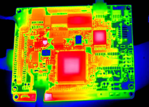
3. Thermal Imaging for Hot Spots
Thermal cameras are becoming more affordable, with basic models under $100. They help detect overheating components or shorts by showing temperature differences on the PCB. For instance, a short circuit might cause a spot to heat up to 70°C while the rest of the board stays at 30°C.
These techniques add depth to your low-cost PCB inspection process, helping you tackle more complex issues without professional equipment.
Tips for Preventing PCB Issues Before Testing
While testing is essential, preventing issues during design and assembly can save you time. Here are a few tips tailored for small-scale projects:
- Double-Check Your Design: Review your schematic and layout for errors before sending it for fabrication. Ensure traces are wide enough (e.g., 0.25mm for low-current signals) to handle expected currents.
- Use Test Points: Include accessible test points in your design for easy probing during testing. Place them near critical components like power rails or signal outputs.
- Start Small: If possible, test smaller sections of your circuit on a breadboard before committing to a full PCB. This can help catch design flaws early.
By taking these steps, you reduce the chances of needing extensive troubleshooting during PCB testing for hobbyists.
Scaling Up: When to Invest in Professional Testing
While DIY PCB testing works well for small projects, there comes a point where professional testing might be worth the investment. If you’re planning to sell your product or produce in larger quantities, consider partnering with a service provider for advanced tests like automated optical inspection (AOI) or functional testing. These methods can catch issues that manual testing might miss, ensuring higher reliability.
For now, though, the strategies outlined above provide a solid foundation for affordable PCB testing that meets the needs of most hobbyists and small-scale developers.
Conclusion: Mastering Cost-Effective PCB Testing
Testing PCBs for small-scale electronics projects doesn’t have to be expensive or complicated. With the right tools and simple PCB test methods, you can ensure your boards work as intended without straining your budget. From visual inspections and continuity tests to building a DIY PCB testing station, these low-cost PCB inspection strategies empower hobbyists and small teams to create reliable prototypes.
Start with the basics, like a multimeter and magnifying glass, and gradually incorporate more advanced techniques as your skills and needs grow. By focusing on affordable PCB testing, you’ll save time, money, and frustration while bringing your electronics projects to life.
Remember, every successful project begins with a well-tested PCB. Use these tips to build confidence in your designs and keep your small-scale projects on track.


