 ALLPCB


When it comes to designing a printed circuit board (PCB), one of the critical decisions you'll make is selecting the right material and copper thickness. Copper thickness, often measured in mils (thousandths of an inch) or ounces per square foot (oz/ft2), plays a significant role in determining the performance, reliability, and compatibility of your PCB for specific applications. Whether you're working on a high-temperature PCB, a flexible PCB, or a standard rigid board, understanding copper thickness compatibility with material properties is essential for success.
In this comprehensive guide, we'll dive deep into how copper thickness impacts PCB material selection, explore its role in various applications, and provide actionable insights to help you make informed decisions. From thermal management to signal integrity, we'll cover the key factors you need to consider to ensure your PCB meets the demands of your project.
Why Copper Thickness Matters in PCB Material Selection
Copper thickness is more than just a specification on a datasheet; it directly affects the electrical, thermal, and mechanical performance of a PCB. The thickness of the copper layer determines how much current the board can carry, how well it dissipates heat, and how it handles high-frequency signals. Choosing the right copper thickness is a balancing act between performance needs and manufacturing constraints, and it must align with the material properties of the PCB substrate.
For instance, a PCB designed for high-power applications may require thicker copper to handle higher current loads without overheating. On the other hand, a high-frequency application might prioritize thinner copper to minimize signal loss. By understanding the interplay between copper thickness and material properties, you can optimize your design for durability and efficiency.
Understanding Copper Thickness: Mils and Ounces Explained
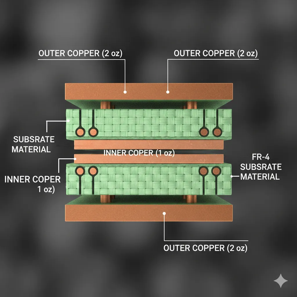
Copper thickness in PCBs is typically measured in two ways: ounces per square foot (oz/ft2) or mils. One ounce of copper per square foot equates to a thickness of about 1.4 mils (0.0014 inches). Common copper thicknesses range from 0.5 oz (0.7 mils) to 4 oz (5.6 mils) or higher for specialized applications.
Here's a quick breakdown of standard copper thicknesses and their uses:
- 0.5 oz (0.7 mils): Used in lightweight, low-power applications or inner layers of multilayer PCBs where minimal current is required.
- 1 oz (1.4 mils): The industry standard for most general-purpose PCBs, balancing cost and performance for moderate current and signal needs.
- 2 oz (2.8 mils): Common in power electronics where higher current capacity and better heat dissipation are needed.
- 3-4 oz (4.2-5.6 mils) or higher: Used in high-power or high-current applications, such as industrial equipment or automotive systems, where thermal management is critical.
The choice of copper thickness must be compatible with the PCB material. For example, flexible PCB materials may struggle with very thick copper due to bending stress, while high-temperature PCB substrates might require thicker copper to manage heat effectively.
How Copper Thickness Affects PCB Performance
Let's explore the specific ways copper thickness influences PCB performance and why it's a crucial factor in material selection.
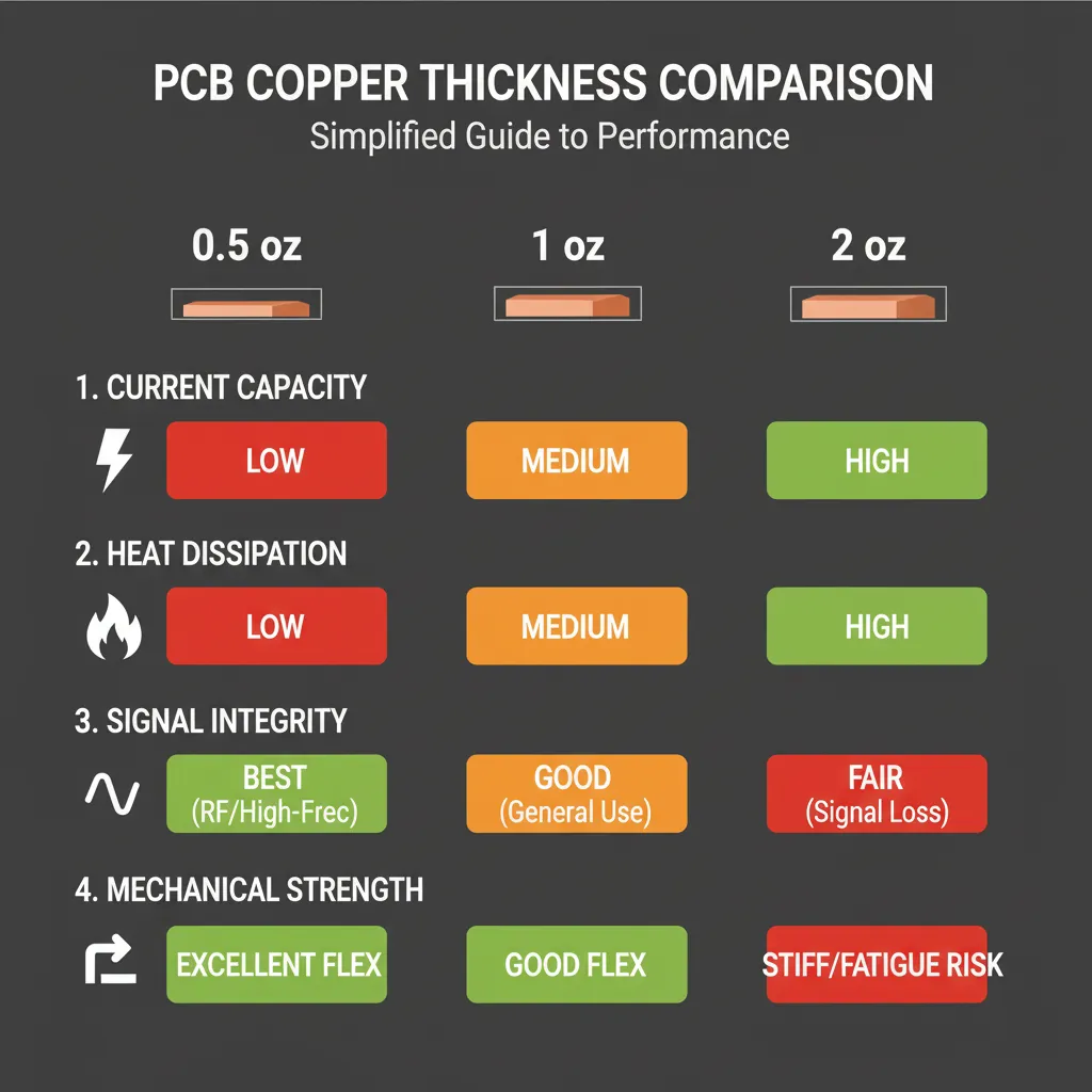
1. Current Carrying Capacity
The thicker the copper, the more current it can carry without overheating. For high-power applications, such as power supplies or motor controllers, a copper thickness of 2 oz or more is often necessary. According to industry standards like IPC-2221, a 1 oz copper trace with a width of 10 mils can carry approximately 1.2 amps at a 10°C temperature rise. Doubling the thickness to 2 oz increases this capacity significantly, reducing the risk of thermal failure.
When selecting a PCB material for high-current applications, ensure the substrate can withstand the associated heat. Materials with high thermal conductivity, such as metal-core laminates, pair well with thicker copper layers.
2. Thermal Management
Thicker copper layers improve heat dissipation, which is critical for high-temperature PCB designs used in environments like automotive or aerospace. For instance, a 3 oz copper layer can reduce the thermal resistance of a board, preventing hotspots that could degrade components or the substrate itself.
However, the PCB material must support this. High-Tg (glass transition temperature) materials, which can withstand temperatures above 150°C, are often paired with thicker copper to ensure reliability under thermal stress.
3. Signal Integrity in High-Frequency Applications
For high-frequency or high-speed digital designs, thinner copper is often preferred. Thicker copper can increase skin effect losses, where high-frequency signals travel along the surface of the conductor, leading to higher impedance and signal degradation. A copper thickness of 0.5 to 1 oz is typically used for RF or microwave applications to maintain signal integrity.
Material selection for high-frequency PCBs often involves low dielectric constant (Dk) substrates like PTFE-based materials, which complement thinner copper layers by minimizing signal loss.
4. Mechanical Strength and Flexibility
In flexible PCB materials, copper thickness directly impacts the board's ability to bend without cracking. Thinner copper, such as 0.5 oz, is ideal for flexible designs because it reduces stress during bending. Thicker copper can cause fatigue in the material over time, leading to failure.
Polyimide, a popular flexible PCB material, offers excellent high-temperature resistance and durability, making it compatible with thinner copper layers for dynamic flex applications.
Copper Thickness Compatibility with PCB Materials
Not all PCB materials are compatible with every copper thickness. The substrate's mechanical and thermal properties must align with the copper layer to avoid issues like delamination, warping, or cracking. Let's look at some common PCB material types and their compatibility with copper thickness.
1. FR-4 for Standard Rigid PCBs
FR-4, a widely used epoxy-based laminate, is compatible with a broad range of copper thicknesses, from 0.5 oz to 4 oz. It's a cost-effective choice for general-purpose applications with moderate thermal and electrical demands. However, for very high-current designs with thick copper (above 3 oz), enhanced FR-4 with higher thermal conductivity may be needed to prevent overheating.
2. High-Temperature PCB Materials
For high-temperature environments, materials like high-Tg FR-4, polyimide, or ceramic-filled laminates are used. These materials can handle the heat generated by thicker copper layers (2-4 oz) in power electronics. For example, polyimide substrates maintain stability at temperatures up to 260°C, making them ideal for automotive or industrial applications with heavy copper.
3. Flexible PCB Materials
Flexible PCB materials, such as polyimide or polyester, are typically paired with thinner copper (0.5-1 oz) to maintain flexibility. Thicker copper can reduce the bend radius and increase the risk of cracking. When designing flexible PCBs, ensure the copper thickness matches the material's mechanical limits to avoid reliability issues.
4. High-Frequency Materials
Materials like Rogers or PTFE-based laminates are used in high-frequency applications due to their low dielectric loss. These substrates work best with thinner copper (0.5-1 oz) to minimize signal attenuation. Thicker copper can introduce parasitic effects, so careful selection is critical for maintaining performance.
Balancing Copper Thickness with Cost and Manufacturability
While thicker copper offers benefits like higher current capacity and better heat dissipation, it also increases manufacturing costs and complexity. Etching thicker copper requires more time and precision, which can lead to higher production expenses. Additionally, not all PCB materials can support very thick copper without risking structural integrity.
For most applications, 1 oz copper provides a good balance of performance and cost. If your design requires heavier copper, consider whether the benefits justify the added expense. Working with a trusted manufacturing partner can help you evaluate these trade-offs and select the optimal copper thickness and material combination for your project.
Key Considerations for Choosing Copper Thickness in Your Application
To make the best decision for your PCB design, keep these factors in mind when evaluating copper thickness and material properties:
- Application Requirements: Determine the electrical, thermal, and mechanical demands of your project. High-power designs need thicker copper, while high-frequency designs benefit from thinner layers.
- Environmental Conditions: For high-temperature PCB applications, pair thicker copper with heat-resistant materials to ensure reliability.
- Signal Integrity Needs: If your design involves high-speed signals, opt for thinner copper and low-loss materials to reduce impedance issues.
- Flexibility: For flexible PCB materials, prioritize thinner copper to maintain bendability and prevent mechanical failure.
- Budget Constraints: Balance performance needs with manufacturing costs, as thicker copper and specialized materials increase expenses.
Practical Examples of Copper Thickness in Action
To illustrate the importance of copper thickness in PCB material selection, let's look at two real-world scenarios:
Scenario 1: Automotive Power Module
An automotive power module operating at high currents (up to 50 amps) and temperatures (up to 125°C) requires a PCB with 3 oz copper to handle the load and dissipate heat. A high-Tg polyimide substrate is chosen for its thermal stability, ensuring the board remains reliable under harsh conditions.
Scenario 2: Wearable Device with Flexible PCB
A wearable fitness tracker needs a flexible PCB to conform to the device's shape. A copper thickness of 0.5 oz is selected to maintain flexibility, paired with a polyimide substrate for durability during repeated bending.
Conclusion: Making an Informed Choice for Your PCB Design
Selecting the right copper thickness is a critical step in PCB material selection, impacting everything from current capacity to thermal management and signal integrity. By understanding the compatibility between copper thickness and material properties, you can design a PCB that meets the specific demands of your application—whether it's a high-temperature PCB, a flexible PCB, or a high-frequency board.
Take the time to evaluate your project's needs, from electrical performance to environmental conditions, and align your choices with the right materials. With careful planning, you can achieve a design that balances performance, reliability, and cost. Whether you're working on a simple prototype or a complex industrial system, the right combination of copper thickness and PCB material will set the foundation for success.


