Overview
The three elements of electromagnetic interference are the source, the propagation path, and the receptor. EMC research addresses these aspects. The fundamental interference suppression techniques are shielding, filtering, and grounding, which are mainly used to interrupt interference transmission paths.
This article discusses EMC filtering. There are several commonly used filtering methods in EMC remediation; below are the main types and the precautions to consider when using them.
Magnetic Filtering
Magnetic filtering introduces magnetic components into the circuit to suppress propagation and reflection of high-frequency noise, thereby reducing electromagnetic interference. Common magnetic elements include ferrite rings, ferrite rods, and coils.
- Frequency range: The frequency response of magnetic filters limits the range of interference frequencies they can suppress. When selecting a magnetic filter, determine the required suppression frequency range and choose accordingly.
- Filter type: Different magnetic filter types perform differently against various interference sources. Ferrite ring filters are typically suitable for high-frequency noise, while coil-based filters are more appropriate for lower-frequency noise. Choose based on the noise characteristics.
- Installation location: Install magnetic filters between the interference source and the affected device to effectively attenuate noise. Avoid placing magnetic components in high-temperature or high-vibration environments to ensure reliability and stability.
- Ground connections: Proper grounding has a significant impact on magnetic filter performance. Correct ground connections can enhance suppression effectiveness and reduce electromagnetic interference.
Capacitive Filtering
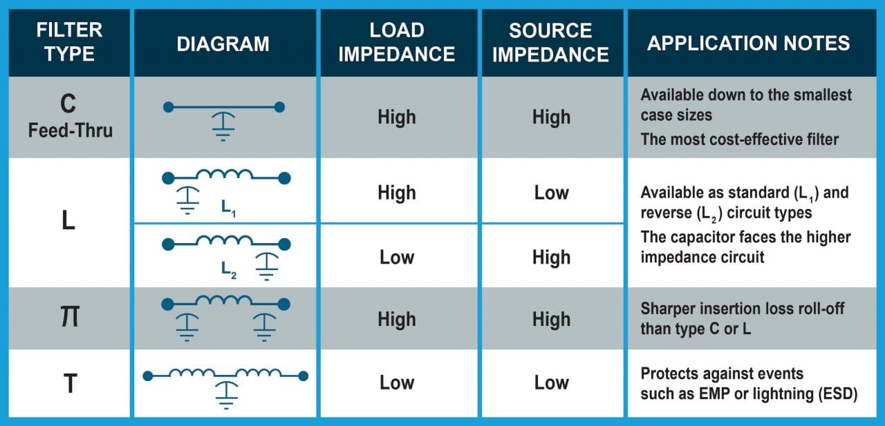
Capacitive filters use capacitors to shunt high-frequency currents to ground, reducing EMI radiation and propagation.
- Capacitor type: Capacitors include tantalum electrolytic, aluminum electrolytic, ceramic, and others. Different types behave differently across frequency ranges, so select the type that matches the application.
- Frequency range: The frequency characteristics of capacitive filters define the range of interference they can effectively suppress. Choose capacitors appropriate for the target frequency band.
- Capacitance selection: Capacitance value directly affects filtering performance. Larger values increase filtering but avoid excessively large capacitance that could negatively impact normal circuit operation.
- Temperature characteristics: Capacitance varies with temperature. At high temperatures, capacitance can decrease and reduce filtering effectiveness. Consider temperature stability when selecting capacitors.
Impedance Filtering
Impedance filters introduce impedance elements so the circuit presents high impedance to signals at certain frequencies, reducing or eliminating interference and noise. Common elements include inductors and transformers.
- Frequency range: The frequency response of impedance filters limits the interference frequencies they can suppress. Determine the required suppression bandwidth and select accordingly.
- Impedance type: Different impedance elements suit different noise types. Inductors are often used for high-frequency noise, while transformers are more suitable for low-frequency noise. Choose based on the interference source and filter characteristics.
- Impedance matching: Filter performance depends on proper impedance matching. If impedances are mismatched, filter effectiveness will be significantly reduced. Ensure matching during design and installation.
- Installation location: Place impedance filters between the interference source and the affected equipment to filter noise effectively. Avoid high-temperature or high-vibration locations to maintain reliability and stability.
- Ground connections: Adequate grounding is key to impedance filter performance. Correct ground connections enhance suppression and reduce EMI.
Band-Pass Filtering
Band-pass filters pass signals within a specified frequency range while suppressing signals outside that range.
- Center frequency: The center frequency of a band-pass filter should match the desired signal frequency to be passed.
- Bandwidth: Bandwidth defines the range of frequencies that will pass. Select an appropriate bandwidth for the application.
- Passband and stopband: The passband is the allowed frequency range and the stopband is the suppressed range. Choose passband and stopband characteristics based on application requirements.
- Filter type: Band-pass designs include second-order, Butterworth, Chebyshev, and other topologies. Different types offer different tradeoffs in ripple, steepness, and phase response; select accordingly.
- Frequency response: A flat and well controlled frequency response without unwanted resonances is important for signal quality. Ensure the design minimizes gain peaking and resonant behavior.
- Stability: Maintain stable performance by using quality components and appropriate PCB layout to ensure consistent frequency and amplitude characteristics.
- Temperature variation: Band-pass filter characteristics can drift with ambient temperature. Consider temperature effects in component selection and design.
Summary
Filtering is a common method for addressing EMC issues. Effective EMC remediation requires comprehensive problem analysis, planning, implementation, verification, continuous improvement, and management. Following a structured process helps resolve electromagnetic compatibility issues and improve system EMC performance.
 ALLPCB


