ALLPCB


Foundational Knowledge
To begin building a quadcopter, a basic understanding of the following areas is essential. It is not necessary to master every detail at the start, but a general familiarity will be beneficial.
- C Programming: Familiarity with fundamental concepts such as structs, pointers, and interrupt handling.
- Basic Electronics: The ability to read schematics and use a multimeter to measure voltage and current.
- Mathematical Concepts: A general understanding of PID control algorithms and quaternion-based attitude estimation.
Quadcopter Hardware Components
Due to weight and payload considerations, quadcopter hardware selection is more constrained than that of a wheeled robot. For beginners, it is recommended to start with a proven hardware kit, many of which are available from online retailers. Once familiar with the basics, you can move on to building custom hardware from open-source designs.
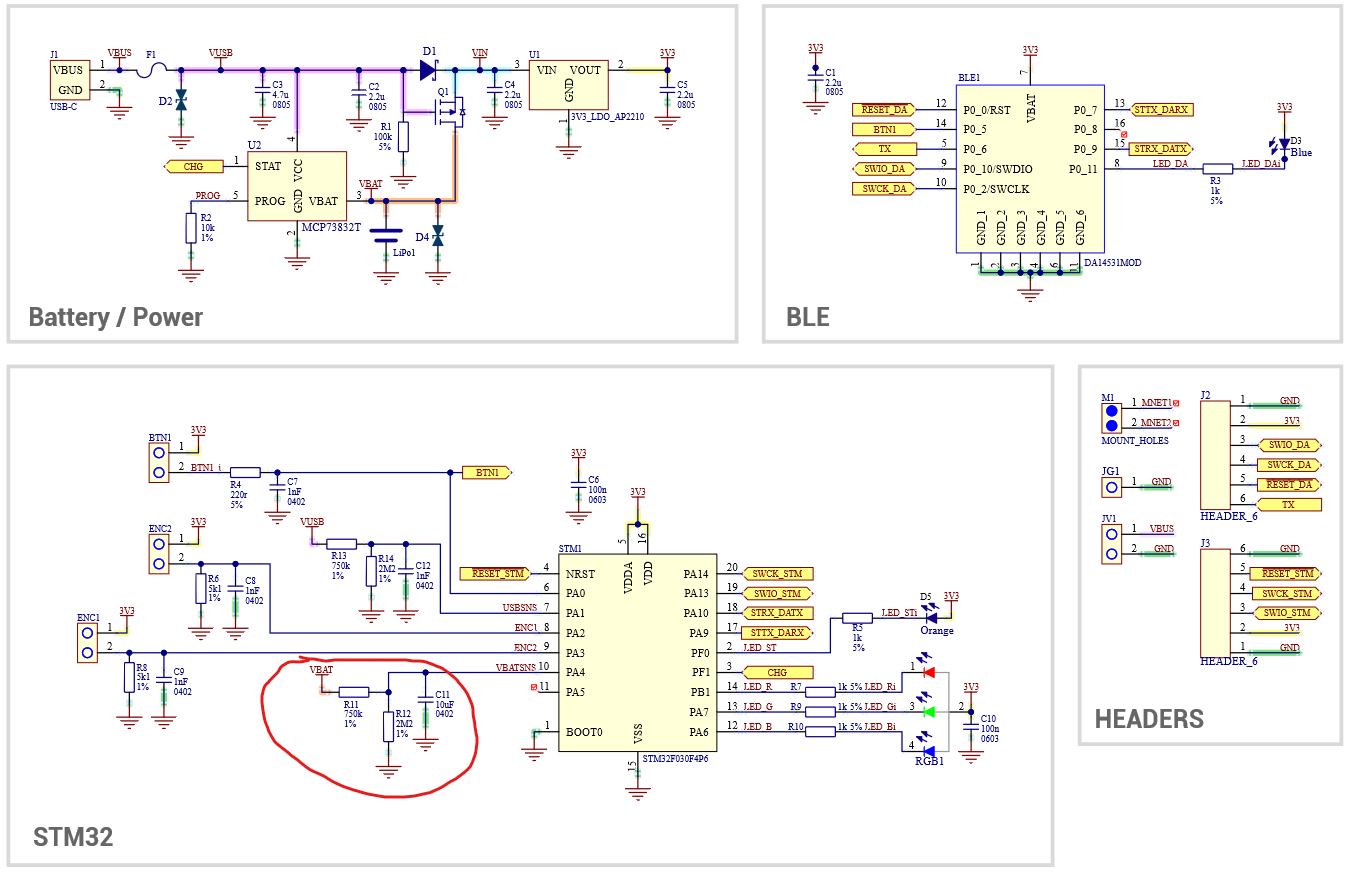
The main hardware components of a quadcopter include:
- Microcontroller (MCU): e.g., STM32F411, for data processing and control logic.
- Sensor: MPU6050 (gyroscope + accelerometer).
- Motors and ESCs: Common choices include 720 coreless motors.
- Remote Controller (RC) and Receiver: An RC transmitter can also be built using an STM32, typically communicating over a 2.4 GHz wireless link.
- Battery and Power Management: 2S-4S LiPo batteries (7.4V-14.8V) are common, requiring a low-noise voltage regulator module (e.g., LM2596).
Setting Up the Development Environment
For beginners, studying the source code of established projects is an effective way to learn. The typical development environment consists of the following tools:
- IDE: STM32CubeIDE (free, with integrated HAL library support).
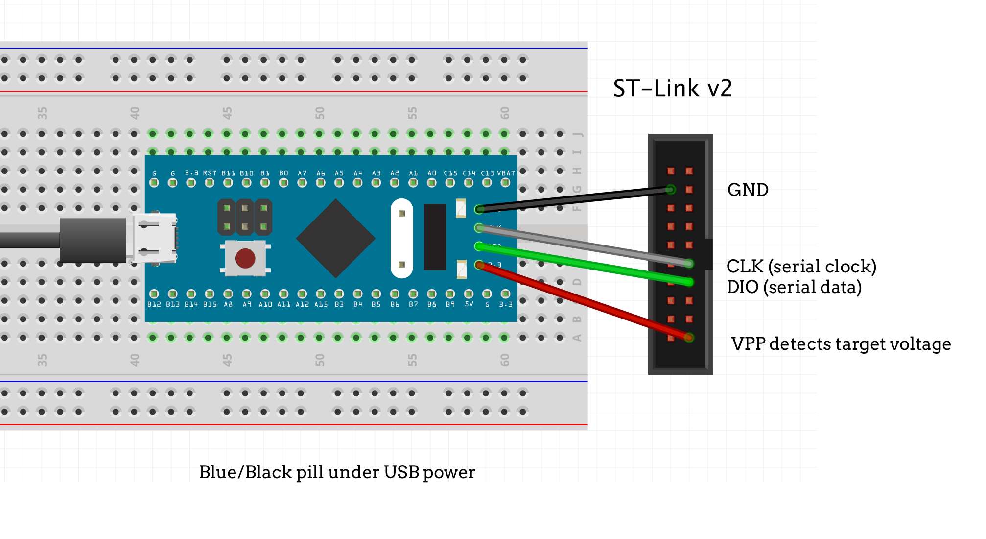
- Programmer/Debugger: ST-Link V2.
- Version Control: Git is highly recommended for source code management.
Key Software Algorithms
While analyzing existing projects is a practical approach, understanding the core algorithms is crucial.
Sensor Data Acquisition (MPU6050)
Read raw data using the I2C protocol, followed by calibration and filtering:
// Example: Reading gyroscope data
void MPU6050_ReadGyro(int16_t *gx, int16_t *gy, int16_t *gz) {
    uint8_t buf[6];
    HAL_I2C_Mem_Read(&hi2c1, MPU6050_ADDR, GYRO_XOUT_H_REG, 1, buf, 6, 100);
    *gx = (buf[0] << 8) | buf[1];
    *gy = (buf[2] << 8) | buf[3];
    *gz = (buf[4] << 8) | buf[5];
}
PID Controller Implementation
typedef struct {
    float Kp, Ki, Kd;
    float integral;
    float prev_error;
} PID;
float PID_Update(PID *pid, float error, float dt) {
    pid->integral += error * dt;
    float derivative = (error - pid->prev_error) / dt;
    pid->prev_error = error;
    return pid->Kp * error + pid->Ki * pid->integral + pid->Kd * derivative;
}
Motor Control
// Set motor PWM duty cycle (0-1000 corresponds to 0%-100%)
void Motor_SetSpeed(uint8_t motor_id, uint16_t duty) {
    TIM_OC_InitTypeDef pwm_config = {0};
    pwm_config.Pulse = duty;
    pwm_config.OCMode = TIM_OCMODE_PWM1;
    HAL_TIM_PWM_ConfigChannel(&htim3, &pwm_config, motor_id);
    HAL_TIM_PWM_Start(&htim3, motor_id);
}
Debugging Tools and Techniques
Effective debugging is a fundamental skill for any electronics project.
- Serial Debugging: Use a serial terminal to view sensor data logs. Specialized drone telemetry tools are also available for more integrated debugging.
- Oscilloscope: An essential tool for checking PWM signal waveforms and protocol timing. Low-cost or open-source hardware options are available for those on a budget.