ALLPCB


If you're a hobbyist looking for cheap PCB diagnostic tools or beginner PCB testing methods, you're in the right place. Diagnosing issues with printed circuit boards (PCBs) doesn't have to break the bank. With tools like a basic multimeter, budget oscilloscopes, or even DIY solutions using platforms like Arduino, you can troubleshoot and test your circuits effectively. In this comprehensive guide, we'll explore affordable tools and techniques for DIY PCB tester setups, including how to use a multimeter for PCB testing, find a budget oscilloscope, and even tackle simple PCB projects to build your skills.
Why PCB Diagnostics Matter for Hobbyists
As a hobbyist, working on electronics projects often means dealing with unexpected issues on your PCBs. Whether it's a short circuit, a broken trace, or a faulty component, diagnosing the problem quickly and accurately is key to saving time and money. While professional diagnostic equipment can cost hundreds or even thousands of dollars, there are plenty of budget-friendly options that deliver reliable results for beginner PCB testing. By learning the right tools and techniques, you can debug your circuits with confidence and take on more complex simple PCB projects.
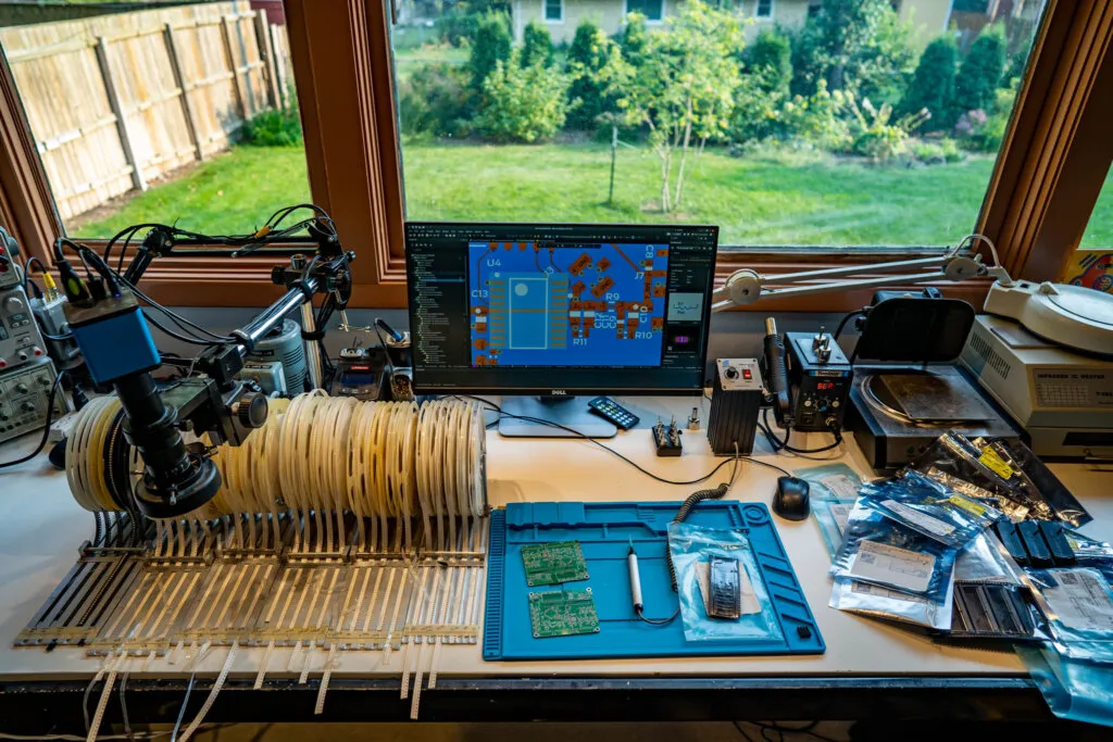
Essential Budget-Friendly PCB Diagnostic Tools for Hobbyists
Let's dive into some of the most accessible and cheap PCB diagnostic tools that every hobbyist should consider. These tools are not only affordable but also versatile enough to handle a wide range of testing needs.
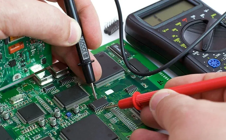
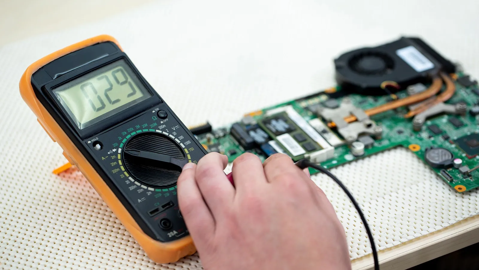
1. Multimeter: The Go-To Tool for PCB Testing
A multimeter is the cornerstone of multimeter PCB testing and one of the most affordable tools you can own. Priced as low as $10 for basic models, a digital multimeter (DMM) allows you to measure voltage, current, and resistance, which are essential for diagnosing PCB issues.
- Voltage Testing: Check if components are receiving the correct voltage (e.g., 5V for most digital circuits or 3.3V for microcontrollers).
- Continuity Testing: Identify broken traces or shorts by testing if current flows between two points. A beep indicates a connection.
- Resistance Measurement: Verify resistor values or detect faulty components by comparing measured resistance to expected values (e.g., a 1kΩ resistor should read close to 1000 ohms).
For hobbyists, a multimeter with a range of 0-20V DC and a continuity buzzer is more than sufficient for most simple PCB projects. Look for models with auto-ranging features to simplify measurements.
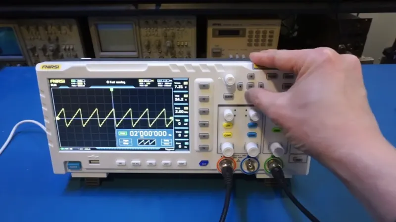
2. Budget Oscilloscope: Visualizing Signals on a Budget
An oscilloscope lets you visualize electrical signals over time, making it invaluable for debugging issues like signal noise or timing errors in your circuits. While professional oscilloscopes can cost over $500, there are budget oscilloscope options for hobbyists starting at around $30 to $100.
- USB Oscilloscopes: These connect to your computer and use software to display waveforms. Many models offer a bandwidth of 1-2 MHz, suitable for low-frequency signals in hobbyist projects.
- Handheld Oscilloscopes: Compact and portable, these often come with a small screen and basic features for under $100. Look for devices with a sampling rate of at least 10 MS/s (mega-samples per second) for decent accuracy.
For beginner PCB testing, a low-bandwidth oscilloscope is often enough to analyze signals in microcontroller projects or audio circuits. Keep in mind that while budget models lack the precision of high-end devices, they are perfect for learning and troubleshooting basic issues.
3. Logic Probe: Simple Digital Signal Testing
A logic probe is a handy, low-cost tool (often under $20) for testing digital circuits. It indicates whether a signal is high (logic 1, typically 5V or 3.3V) or low (logic 0, near 0V) with a simple LED or sound indicator. This is especially useful for debugging microcontroller-based projects or checking if a pin on your PCB is outputting the expected state.
Logic probes are ideal for hobbyists working on simple PCB projects involving digital components like LEDs, sensors, or basic ICs. They are easy to use and require no complex setup, making them a great addition to your cheap PCB diagnostic tools collection.
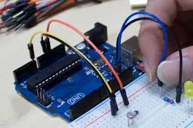
4. DIY PCB Tester with Arduino
For those who love a hands-on approach, building a DIY PCB tester using an Arduino is an affordable and educational option. Arduino boards, starting at around $20 for clones or $25 for originals, can be programmed to test various aspects of a PCB. With the right code and a few additional components, you can create custom diagnostic tools.
- Continuity Tester: Use an Arduino to check for shorts or open circuits by sending a small current through test points and reading the results via analog pins.
- Voltage Monitor: Measure voltages across components using the Arduino’s analog-to-digital converter (ADC), which can read voltages from 0 to 5V with a resolution of about 4.9mV per step (1024 steps over 5V).
- Signal Generator: Program the Arduino to output test signals (e.g., square waves at 1kHz) to stimulate your PCB and observe responses with a multimeter or oscilloscope.
Arduino PCB diagnostics are perfect for hobbyists who want to combine learning with practical testing. Plus, there are countless online tutorials and community projects to guide you through building your own tester.
Budget-Friendly PCB Testing Techniques for Beginners
Beyond tools, knowing the right techniques can save you time and frustration during beginner PCB testing. Here are some practical methods to diagnose issues using the tools mentioned above.
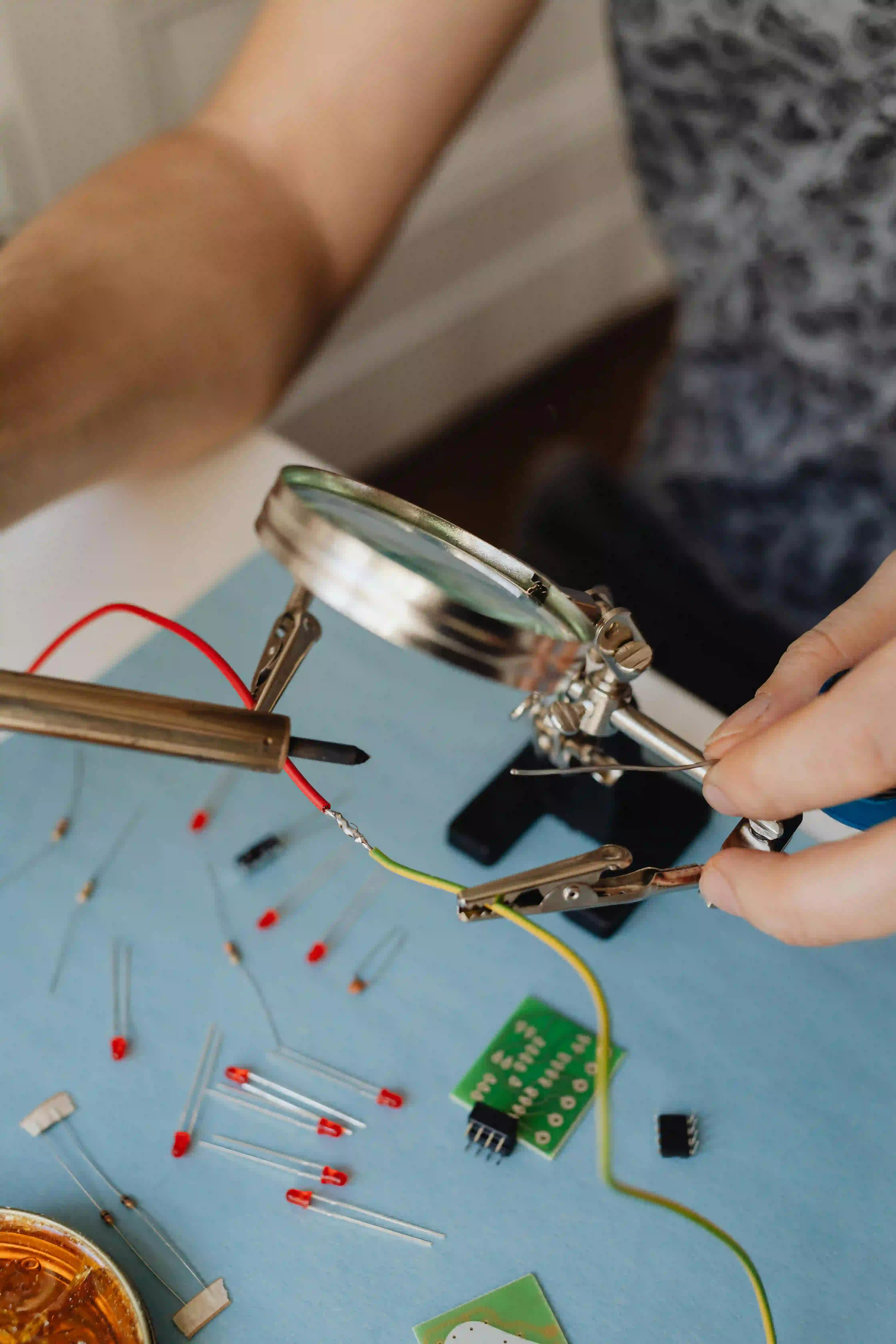
1. Visual Inspection: The First Step
Before using any tools, start with a thorough visual inspection of your PCB. Look for obvious issues like burnt components, cracked solder joints, or misaligned parts. Use a magnifying glass or a smartphone camera with zoom to spot tiny defects. This free technique can often reveal problems without the need for advanced equipment.
2. Continuity Testing with a Multimeter
Use your multimeter in continuity mode to check for broken traces or shorts. Place the probes on two points of a trace; if you hear a beep, the connection is intact. If there’s no sound, there’s likely a break. For shorts, test between adjacent traces or pads—if there’s continuity where there shouldn’t be, you’ve found a short circuit.
This method is a cornerstone of multimeter PCB testing and works well for diagnosing issues in simple PCB projects. It’s quick, easy, and requires no expensive gear.
3. Power-On Testing with Voltage Measurements
Once you’ve confirmed the board’s physical integrity, power it on and use a multimeter to measure voltages at key points. Compare the readings to your circuit’s expected values. For example, if a microcontroller pin should output 5V but reads only 2.3V, there might be a problem with the power supply or a connected component drawing too much current.
Be cautious with live circuits, and always double-check your multimeter’s settings to avoid damaging the tool or the PCB.
4. Signal Analysis with a Budget Oscilloscope
For dynamic issues like signal distortion or timing problems, use a budget oscilloscope to observe waveforms. Connect the probe to a test point (e.g., the output of an oscillator circuit) and check if the signal matches the expected shape and frequency. For instance, a square wave at 1kHz should have clean edges and a period of 1 millisecond. If the edges are rounded or the frequency is off, you might have a capacitor or resistor issue.
This technique is especially useful for audio circuits, motor drivers, or any project where timing and signal integrity are critical.
5. Component Testing: Isolate the Fault
If a specific area of the PCB seems problematic, test individual components. Use a multimeter to check resistors, capacitors, and diodes for proper values or behavior. For example, a diode should conduct in one direction (showing a voltage drop of about 0.7V for silicon diodes) and block in the other (showing infinite resistance). If it fails this test, it’s likely defective.
For complex ICs, consider swapping with a known good component if you have a spare. This trial-and-error method works well for hobbyists without advanced diagnostic gear.
Simple PCB Projects to Build Diagnostic Skills
Practice makes perfect, and working on simple PCB projects is a great way to hone your diagnostic skills. Here are a few beginner-friendly ideas that also help you test your tools and techniques.
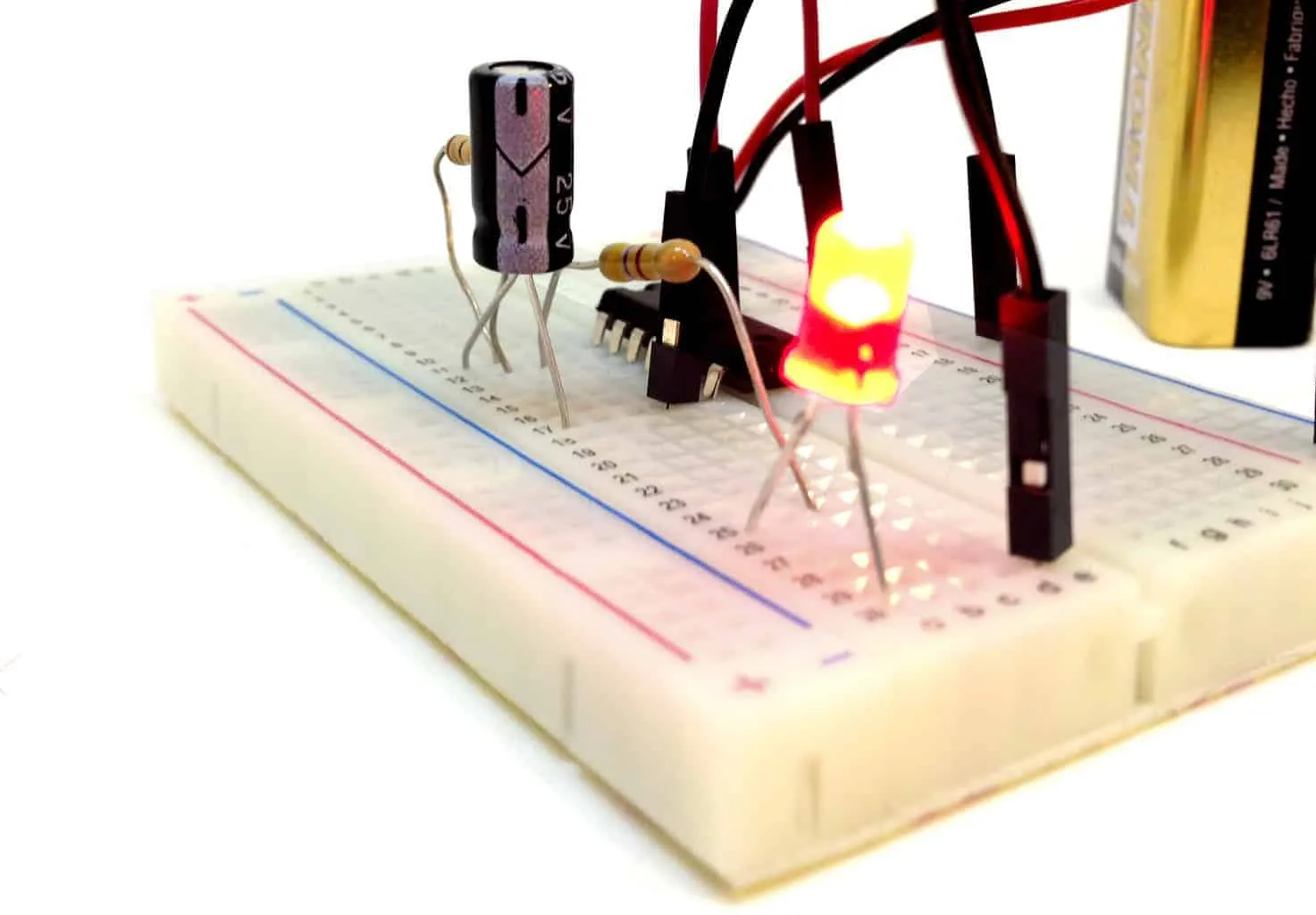
1. LED Blinking Circuit
Build a basic circuit with a microcontroller or a 555 timer IC to blink an LED at a specific rate (e.g., 1Hz). Use a multimeter to verify voltage across the LED (typically 2-3V depending on color) and an oscilloscope to check the timing of the square wave driving it. If the LED doesn’t blink as expected, troubleshoot using continuity and voltage tests.
2. Voltage Divider Tester
Create a voltage divider with two resistors (e.g., 1kΩ and 2kΩ) to step down a 9V input to 6V and 3V at different points. Measure the voltages with a multimeter to confirm they match theoretical values. If they don’t, check for incorrect resistor values or poor connections. This project is excellent for practicing multimeter PCB testing.
3. Arduino-Based Sensor Circuit
Design a circuit with an Arduino and a simple sensor (like a photoresistor or temperature sensor). Program the Arduino to output sensor data to a serial monitor. Use Arduino PCB diagnostics by checking voltages at sensor pins and observing signal changes with an oscilloscope. This helps you learn both hardware and software debugging.
Tips for Choosing the Right Budget Tools
With so many options available, selecting the best cheap PCB diagnostic tools can feel overwhelming. Here are some practical tips to guide your purchases.
- Prioritize Versatility: Choose tools like a multimeter or Arduino that can serve multiple purposes, from basic testing to complex diagnostics.
- Read Reviews: Look for user feedback on budget tools to ensure reliability. A $30 oscilloscope with good reviews is often better than a $50 one with poor performance.
- Start Small: If you’re new to beginner PCB testing, begin with a basic multimeter and expand to oscilloscopes or logic probes as your skills grow.
- Consider DIY Options: Building a DIY PCB tester with an Arduino can save money and teach you valuable skills.
Common PCB Issues and How to Diagnose Them
Understanding common PCB problems can help you apply the right diagnostic techniques. Here are a few frequent issues and how to tackle them with budget tools.
- Short Circuits: Use a multimeter in continuity mode to find unintended connections between traces or pads. Look for solder bridges or damaged insulation.
- Open Circuits: Test traces with a multimeter to locate breaks. A lack of continuity indicates a disconnected path.
- Faulty Components: Measure voltage drops or resistance across components to identify failures. For capacitors, a multimeter with capacitance mode (if available) can detect issues.
- Signal Issues: Use a budget oscilloscope to check for noise, distortion, or incorrect frequencies in oscillating circuits.
Conclusion: Start Diagnosing PCBs on a Budget Today
Diagnosing PCB issues as a hobbyist doesn’t require expensive equipment. With cheap PCB diagnostic tools like a multimeter, a budget oscilloscope, or even a DIY PCB tester built with an Arduino, you can troubleshoot effectively without spending a fortune. By mastering techniques like multimeter PCB testing and working on simple PCB projects, you’ll build confidence in beginner PCB testing and take your electronics skills to the next level.
Start small, invest in versatile tools, and practice regularly. Over time, you’ll be able to handle more complex diagnostics with ease. Whether you’re debugging a homemade circuit or refining your Arduino PCB diagnostics, these budget-friendly options and techniques will serve you well in your hobbyist journey.