 ALLPCB


When designing printed circuit boards (PCBs) for avionics systems, selecting the right substrate material is critical to ensure performance, reliability, and safety under extreme conditions. Avionics PCBs must withstand high temperatures, vibrations, and humidity while maintaining signal integrity and structural stability. So, what are the best materials for avionics PCB substrate material selection? Key options include FR-4, polyimide, and Rogers materials, each with unique properties suited for specific applications. Factors like thermal resistance, coefficient of thermal expansion (CTE) matching, and dielectric performance play a major role in this decision.
In this comprehensive guide, we’ll dive deep into the world of high temperature PCB material for avionics, explore the benefits and limitations of popular substrates like Rogers material for avionics PCB, FR-4 for avionics PCB, and polyimide PCB for avionics, and explain the importance of CTE matching for avionics PCB. Whether you're an engineer working on aerospace projects or a designer seeking reliable materials, this blog will help you make informed choices for high-reliability systems.
Why Substrate Material Selection is Crucial for Avionics PCBs
Avionics systems operate in some of the harshest environments, from extreme altitudes with freezing temperatures to high-heat conditions near engines. PCBs in these systems control critical functions like navigation, communication, and flight control, so any failure can have catastrophic consequences. The substrate material—the core layer of a PCB—directly impacts its ability to handle thermal stress, maintain electrical performance, and resist mechanical failure.
Choosing the wrong substrate can lead to issues like delamination, signal loss, or cracking due to thermal expansion mismatches. For instance, a material with poor thermal conductivity might overheat, causing components to fail at temperatures as high as 150°C, which are common in avionics environments. On the other hand, a well-selected substrate ensures long-term reliability, even under cyclic temperature changes from -55°C to 125°C, as specified in many aerospace standards.
Key Factors in Selecting Avionics PCB Substrate Materials
Before diving into specific materials, let’s break down the critical factors to consider when selecting a substrate for avionics PCBs. These factors ensure the board meets the demanding requirements of aerospace applications.
1. Thermal Performance and High-Temperature Resistance
Avionics systems often face temperatures exceeding 100°C, especially in engine control units or near heat-generating components. A high temperature PCB material for avionics must have a high glass transition temperature (Tg), which indicates the point at which the material softens and loses structural integrity. For example, materials with a Tg above 170°C are often preferred for high-heat environments to prevent warping or degradation.
2. Coefficient of Thermal Expansion (CTE) Matching
CTE matching for avionics PCB is vital to prevent stress and cracking during temperature fluctuations. CTE measures how much a material expands or contracts with temperature changes. If the substrate’s CTE differs significantly from that of the copper traces or mounted components (typically around 17 ppm/°C for copper), it can lead to mechanical failure. Materials with a CTE close to copper or ceramic components reduce the risk of delamination and solder joint failure.
3. Dielectric Properties for Signal Integrity
High-frequency signals are common in avionics systems for communication and radar applications. The substrate’s dielectric constant (Dk) and dissipation factor (Df) affect signal speed and loss. A low Dk (e.g., 2.2 to 3.5) and low Df (e.g., below 0.005) are ideal for minimizing signal delay and maintaining integrity at frequencies above 1 GHz.
4. Mechanical Strength and Vibration Resistance
Avionics PCBs must endure constant vibration and mechanical shock during flight. Substrates need high tensile strength and flexibility to resist cracking or breaking under stress. This is especially important for materials used in flexible or rigid-flex designs.
5. Moisture and Chemical Resistance
Exposure to humidity, condensation, and chemicals like fuel or hydraulic fluids is common in avionics environments. A good substrate should resist moisture absorption (ideally below 0.2%) and maintain performance when exposed to harsh substances.
Popular Substrate Materials for Avionics PCBs
Now that we understand the key factors, let’s explore the most commonly used materials for avionics PCBs, focusing on their strengths, limitations, and ideal applications.
FR-4 for Avionics PCB: Cost-Effective but Limited
FR-4 for avionics PCB is one of the most widely used substrate materials due to its affordability and versatility. Made from woven fiberglass and epoxy resin, FR-4 offers decent mechanical strength and is suitable for many standard applications. Its dielectric constant typically ranges from 4.2 to 4.5, making it acceptable for low- to mid-frequency circuits.
However, FR-4 has limitations in high-reliability avionics systems. Its Tg is often around 130°C to 140°C for standard grades, which is insufficient for extreme heat conditions. High-Tg FR-4 variants (Tg up to 170°C) are available but still fall short compared to other materials for high temperature PCB material for avionics. Additionally, its CTE (around 14-17 ppm/°C) is close to copper, but it may not match well with ceramic components, increasing the risk of thermal stress.
Use Case: FR-4 is best for non-critical avionics systems or prototypes where cost is a major concern and operating temperatures remain below 100°C.
Polyimide PCB for Avionics: High-Temperature Champion
Polyimide PCB for avionics is a go-to choice for applications requiring exceptional thermal resistance. Polyimide substrates have a Tg exceeding 250°C, making them ideal for environments with temperatures up to 200°C or higher. They also offer excellent chemical resistance and flexibility, which is why they are often used in flexible and rigid-flex PCBs for avionics.
The CTE of polyimide (around 12-20 ppm/°C) can be tailored to match copper or other materials, reducing thermal stress. However, its dielectric constant (around 3.5) and dissipation factor (0.008-0.01) are not as favorable as some high-frequency materials, so it may not be the best choice for radar or communication systems operating above 5 GHz.
Use Case: Polyimide shines in engine control units and other high-temperature zones where thermal stability is non-negotiable.
Rogers Material for Avionics PCB: High-Frequency Performance
Rogers material for avionics PCB is a premium option designed for high-frequency and high-performance applications. These substrates, made from specialized laminates, offer a low dielectric constant (as low as 2.2) and an extremely low dissipation factor (below 0.001), ensuring minimal signal loss at frequencies up to 10 GHz or higher. This makes them perfect for avionics radar, satellite communication, and navigation systems.
Additionally, Rogers materials provide excellent thermal stability with Tg values often above 200°C and low CTE values (around 10-17 ppm/°C) for better CTE matching for avionics PCB. Their downside is cost—Rogers substrates are significantly more expensive than FR-4 or even polyimide, which can limit their use to critical, high-budget projects.
Use Case: Rogers materials are ideal for high-frequency avionics systems where signal integrity is paramount, such as in advanced communication modules.
Comparing Substrate Materials: Which One Suits Your Needs?
To make the selection process easier, let’s compare the three main materials based on key parameters for avionics applications:
- Thermal Resistance: Polyimide leads with a Tg above 250°C, followed by Rogers (above 200°C), while FR-4 lags at 130-170°C.
- High-Frequency Performance: Rogers excels with a Dk of 2.2-3.5 and Df below 0.001, while polyimide (Dk 3.5, Df 0.008) and FR-4 (Dk 4.2-4.5, Df 0.02) are less suitable for GHz frequencies.
- CTE Matching: All three can be engineered for reasonable CTE values (10-20 ppm/°C), but Rogers and polyimide offer more precise matching options.
- Cost: FR-4 is the most affordable, polyimide is moderately priced, and Rogers is the most expensive.
Ultimately, the choice depends on your specific application. For high-temperature zones, opt for polyimide. For high-frequency needs, choose Rogers. For budget-conscious, less demanding projects, FR-4 may suffice.
Advanced Considerations for High-Reliability Avionics PCBs
Beyond material selection, there are additional considerations to ensure the reliability of avionics PCBs in extreme conditions.
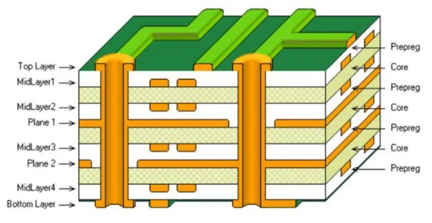
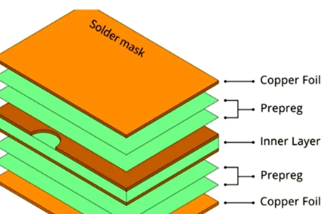
Multilayer Designs and Thermal Management
Avionics PCBs often use multilayer constructions to accommodate complex circuitry. The substrate must support consistent interlayer bonding and thermal dissipation. Adding thermal vias or using materials with high thermal conductivity (e.g., 1.0 W/m·K or higher) can help manage heat in dense designs.
Compliance with Aerospace Standards
Materials must meet strict aerospace standards like MIL-PRF-31032 or IPC-4101 for reliability and performance. Ensure that the chosen substrate has been tested for outgassing, flammability (UL 94V-0 rating), and long-term durability under thermal cycling.
Hybrid Material Solutions
In some cases, combining materials in a hybrid PCB can optimize performance. For example, using Rogers for high-frequency layers and polyimide for high-temperature sections can balance cost and functionality in a single board.
How to Choose the Right Substrate for Your Avionics Project
Selecting the right avionics PCB substrate material involves a step-by-step evaluation of your project’s needs:
- Define Operating Conditions: Determine the temperature range, frequency requirements, and environmental exposures your PCB will face.
- Prioritize Key Properties: Focus on thermal resistance for high-heat areas or dielectric performance for high-frequency signals.
- Balance Cost and Performance: Choose a material that meets your technical needs without exceeding budget constraints.
- Test and Validate: Work with a trusted PCB manufacturer to prototype and test the material under simulated conditions.
By following this approach, you can ensure that your avionics system operates reliably, even in the most challenging environments.
Conclusion: Building Reliability with the Right Material
In the world of avionics, where safety and performance are non-negotiable, selecting the right substrate material can make or break a project. Whether you opt for the cost-effective FR-4 for avionics PCB, the thermally robust polyimide PCB for avionics, or the high-frequency optimized Rogers material for avionics PCB, understanding your application’s requirements is key. Don’t overlook the importance of high temperature PCB material for avionics and CTE matching for avionics PCB to prevent failures caused by thermal stress.
At ALLPCB, we’re committed to helping engineers and designers navigate these complex decisions. With a wide range of substrate materials and expertise in high-reliability PCB manufacturing, we can support your avionics projects from prototype to production. Choose wisely, and build systems that soar above the rest.


