 ALLPCB


Marine environments pose unique challenges for PCB assembly due to harsh conditions like saltwater exposure, humidity, and temperature extremes. Whether you're working on marine PCB SMT assembly or marine PCB through-hole assembly, following best practices is critical for ensuring reliability and longevity. In this comprehensive guide, we'll explore proven techniques for assembling PCBs for marine applications, covering everything from component selection to soldering methods like wave soldering marine PCBs and reflow soldering marine PCBs. Let’s dive into the details to help you achieve durable and high-performing marine electronics.
Why Marine PCB Assembly Requires Special Attention
Marine electronics must withstand constant exposure to moisture, salt, and vibrations, which can lead to corrosion, electrical shorts, and mechanical failures. A poorly assembled PCB in a marine setting might fail within months, whereas a well-designed and assembled board can last years, even in harsh conditions. For instance, studies show that corrosion from saltwater can degrade unprotected copper traces by up to 50% within a year under constant exposure. This is why specialized techniques and materials are essential for marine PCB assembly.
Key Challenges in Marine PCB Assembly
Before diving into the best practices, it’s important to understand the specific challenges marine PCBs face:
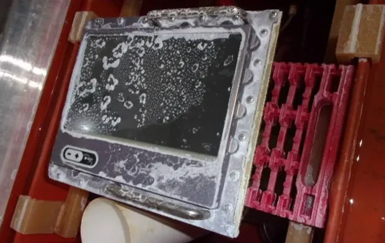
- Corrosion: Saltwater and humidity can corrode metal components and traces, leading to signal loss or complete failure.
- Temperature Fluctuations: Marine environments often experience extreme temperature changes, which can cause thermal stress on components and solder joints.
- Vibrations and Shock: Constant movement from waves or engine vibrations can loosen components or crack solder joints.
- Moisture Ingress: Water can seep into unprotected boards, causing shorts or degradation over time.
With these challenges in mind, let’s explore the best practices for reliable marine PCB SMT assembly and marine PCB through-hole assembly.
Best Practices for Marine PCB SMT Assembly
Surface Mount Technology (SMT) is widely used in modern electronics due to its ability to support high component density and compact designs. However, for marine applications, extra care is needed during assembly to ensure durability. Here are the top practices for marine PCB SMT assembly:
1. Choose Corrosion-Resistant Materials
For SMT components in marine environments, prioritize materials that resist corrosion. Opt for gold-plated or nickel-palladium-gold (NiPdAu) finishes on PCB pads and component leads. These finishes can reduce corrosion rates by up to 70% compared to standard tin-lead finishes when exposed to saltwater mist, based on industry testing standards like IPC-TM-650.
2. Optimize Solder Paste and Reflow Profiles
When using reflow soldering marine PCBs, selecting the right solder paste and reflow profile is crucial. Use no-clean, water-resistant solder pastes with high activation flux to ensure strong bonds even in humid conditions. Maintain a reflow temperature profile with a peak of around 245°C for lead-free solder to avoid thermal shock, which can weaken joints under temperature cycling common in marine settings.
3. Apply Conformal Coating for Protection
After SMT assembly, apply a conformal coating to shield the board from moisture and salt. Silicone or acrylic-based coatings are ideal for marine environments as they provide a barrier against water ingress while maintaining flexibility under thermal expansion. Ensure the coating thickness is between 25-75 micrometers for optimal protection without interfering with component performance.
4. Use Automated Optical Inspection (AOI)
Incorporate AOI during the SMT assembly process to detect defects like misaligned components or insufficient solder. AOI systems can achieve defect detection rates of over 95%, ensuring that potential issues are caught before the PCB is deployed in a marine environment where repairs are difficult.
Best Practices for Marine PCB Through-Hole Assembly
Through-hole technology (THT) is often used for components that require strong mechanical bonds, such as connectors or high-power devices. For marine applications, THT offers robustness but requires specific techniques for reliability. Here are the best practices for marine PCB through-hole assembly:
1. Reinforce Mechanical Stability
Through-hole components are ideal for marine electronics due to their strong mechanical attachment to the PCB. To enhance stability, use larger pad sizes (at least 1.5 times the hole diameter) and ensure proper soldering to fill the through-hole completely. This reduces the risk of joint failure under vibration, which can reach frequencies of 10-50 Hz on marine vessels.
2. Select Durable Components
For component selection marine assembly, choose through-hole components with high-temperature ratings (up to 125°C) and corrosion-resistant leads. Stainless steel or gold-plated pins are excellent choices to prevent degradation in salty conditions.
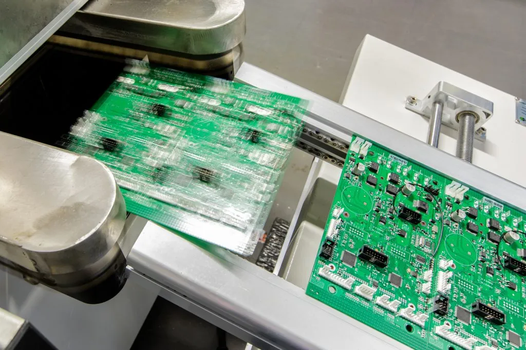
3. Master Wave Soldering Techniques
When using wave soldering marine PCBs, control the solder wave height and temperature to avoid thermal stress on components. A typical wave soldering temperature for lead-free solder is around 260°C, with a conveyor speed of 1.5-2 meters per minute to ensure even solder distribution. Preheating the PCB to 100-120°C before soldering also minimizes thermal shock.
4. Inspect Solder Joints Thoroughly
After wave soldering, inspect each through-hole solder joint for voids or cracks using X-ray inspection if possible. A well-formed joint should have a fillet height of at least 1 mm above the PCB surface to ensure mechanical strength against marine vibrations.
Component Selection for Marine Assembly
Choosing the right components is a cornerstone of reliable marine PCB assembly. Poor component selection can lead to premature failure, even with the best soldering techniques. Here are key considerations for component selection marine assembly:
1. Prioritize Environmental Ratings
Select components with high IP (Ingress Protection) ratings, such as IP67 or IP68, to ensure resistance to water and dust. Capacitors, resistors, and ICs should also have extended temperature ranges (e.g., -40°C to 85°C) to handle marine conditions.
2. Opt for Sealed or Encapsulated Components
Use sealed connectors and encapsulated power modules to prevent moisture ingress. For instance, epoxy-encapsulated transformers can withstand humidity levels of up to 95% without performance degradation.
3. Avoid Components with Exposed Metal
Minimize the use of components with exposed metal surfaces unless they are coated with corrosion-resistant materials. Unprotected aluminum capacitors, for example, can corrode within weeks in a marine environment.
Soldering Techniques for Marine PCBs: Wave vs. Reflow
Soldering is a critical step in PCB assembly, and the method you choose depends on the type of components and the environmental demands. Let’s compare wave soldering marine PCBs and reflow soldering marine PCBs to understand their applications in marine assembly.
Wave Soldering for Through-Hole Components
Wave soldering is the go-to method for through-hole components in marine PCBs. It allows for rapid, bulk soldering by passing the PCB over a molten solder wave. To optimize results, use a dual-wave soldering machine to ensure complete hole filling, and apply a flux with high corrosion resistance to protect joints long-term.
Reflow Soldering for SMT Components
Reflow soldering is ideal for SMT components due to its precision and ability to handle high-density layouts. For marine PCBs, use a nitrogen atmosphere during reflow to reduce oxidation of solder joints, which can be a significant issue in humid conditions. Maintain a controlled cooling rate (1-3°C per second) after reflow to prevent microcracks in solder joints caused by thermal stress.
Additional Tips for Reliable Marine PCB Assembly
Beyond soldering and component selection, here are additional strategies to enhance the reliability of marine PCBs:
- Use Thicker PCBs: Opt for PCBs with a thickness of 1.6 mm or more to reduce warping during soldering and improve mechanical durability.
- Design for Redundancy: Include redundant traces or components in critical circuits to ensure functionality even if one part fails due to corrosion or vibration.
- Test Under Simulated Conditions: Before deployment, test assembled PCBs in a salt fog chamber for at least 96 hours to simulate marine exposure and identify weaknesses.
Conclusion: Building Durable Marine Electronics with Proper Assembly
Assembling PCBs for marine applications demands careful planning and execution to overcome the challenges of saltwater, humidity, and vibrations. By following best practices for marine PCB SMT assembly and marine PCB through-hole assembly, you can create electronics that perform reliably for years. Focus on corrosion-resistant materials, precise soldering techniques like wave soldering marine PCBs and reflow soldering marine PCBs, and thoughtful component selection marine assembly to ensure durability. With these strategies, your marine electronics will be ready to tackle the toughest conditions on the open water.
At ALLPCB, we’re committed to supporting your marine PCB projects with high-quality manufacturing solutions tailored to your needs. Let’s build electronics that stand the test of time, even in the harshest environments.


