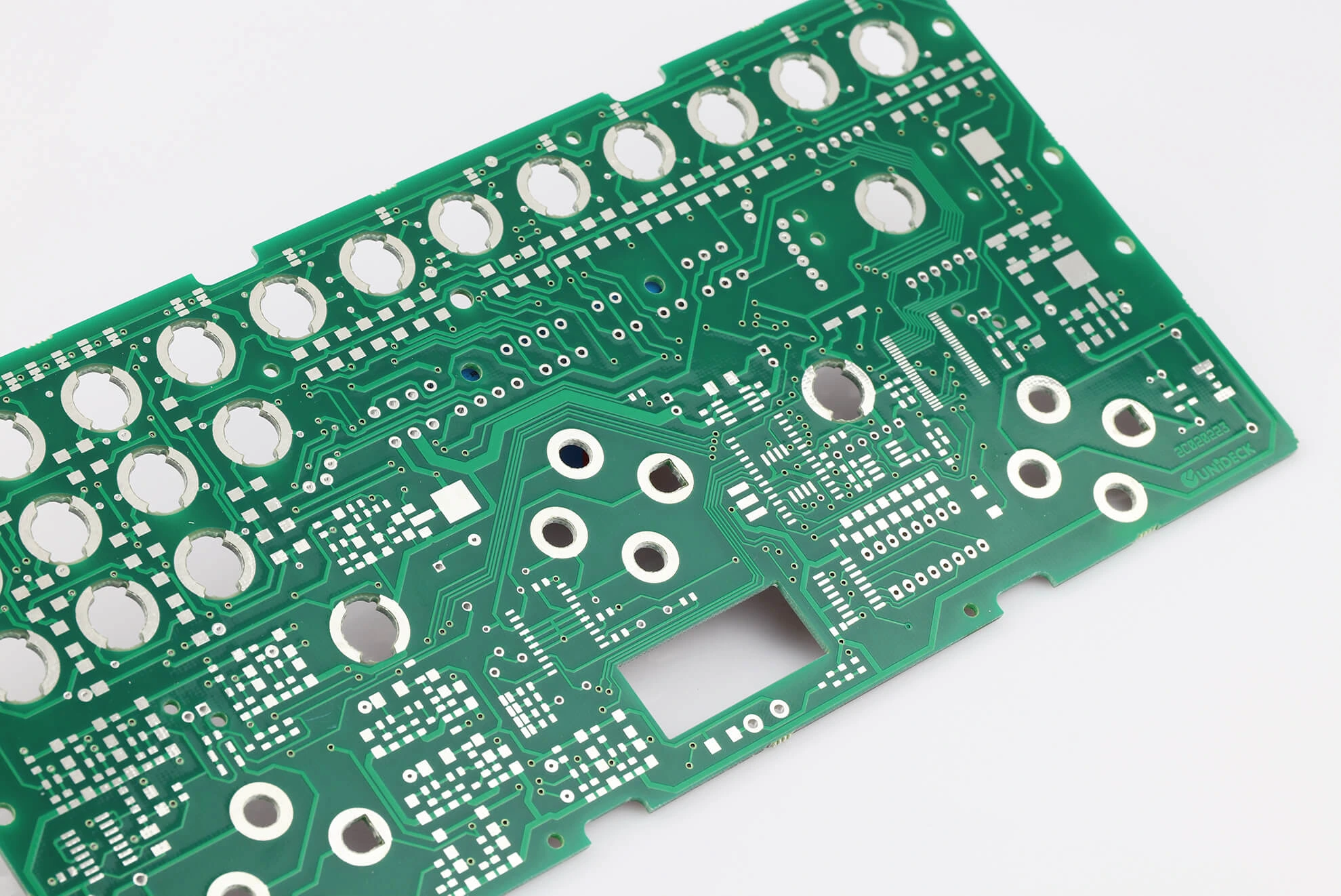
In the fast-evolving world of autonomous vehicles, reliable communication between systems is critical for safety and performance. One of the most trusted methods for achieving this is through CAN (Controller Area Network) bus communication. If you're designing a PCB for autonomous vehicle control, implementing CAN bus communication can ensure seamless data exchange between sensors, actuators, and control units. This blog post will guide you through the essentials of integrating CAN bus into your PCB design, covering key aspects like layout guidelines, transceiver selection, termination techniques, signal integrity, and automotive network design.
Whether you're an engineer working on cutting-edge autonomous systems or a designer looking to optimize your PCB for automotive applications, this comprehensive guide will provide actionable insights. Let’s dive into the details of designing a robust CAN bus system for autonomous vehicle control.
What Is CAN Bus and Why Is It Essential for Autonomous Vehicles?
CAN bus is a robust communication protocol widely used in automotive systems to enable real-time data exchange between electronic control units (ECUs). In autonomous vehicles, where split-second decisions rely on data from cameras, LiDAR, radar, and other sensors, CAN bus offers a reliable, fault-tolerant, and efficient communication network. Its ability to handle high-speed data with minimal errors makes it a go-to choice for automotive network PCB design.
Unlike other communication protocols, CAN bus operates on a two-wire differential system, reducing wiring complexity while maintaining high noise immunity. This is especially important in the harsh electromagnetic environment of a vehicle. By implementing CAN bus on your PCB, you ensure that critical systems like braking, steering, and sensor fusion communicate effectively, enhancing the safety and reliability of autonomous driving.
CAN Bus PCB Layout Guidelines for Optimal Performance
Designing a PCB for CAN bus communication requires careful attention to layout to prevent signal degradation and interference. Here are some key CAN bus PCB layout guidelines to follow:
- Minimize Trace Lengths: Keep the CAN high (CANH) and CAN low (CANL) traces as short as possible to reduce signal delay and potential noise pickup. Ideally, route these traces as a differential pair with a consistent spacing of about 0.1 to 0.2 mm, depending on your PCB stack-up.
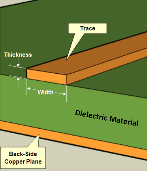
- Maintain Impedance Matching: Ensure the differential impedance of the CAN bus traces is around 120 ohms, which is the standard for CAN networks. Use a PCB design tool to calculate trace width and spacing based on your board’s dielectric constant (typically 4.5 for FR4 material).
- Avoid Sharp Corners: Route traces with smooth curves or 45-degree angles instead of 90-degree bends to minimize signal reflection and electromagnetic interference (EMI).
- Ground Plane Integrity: Place a solid ground plane beneath the CAN bus traces to provide a low-impedance return path for signals. Avoid splitting the ground plane under the traces, as this can disrupt signal integrity.
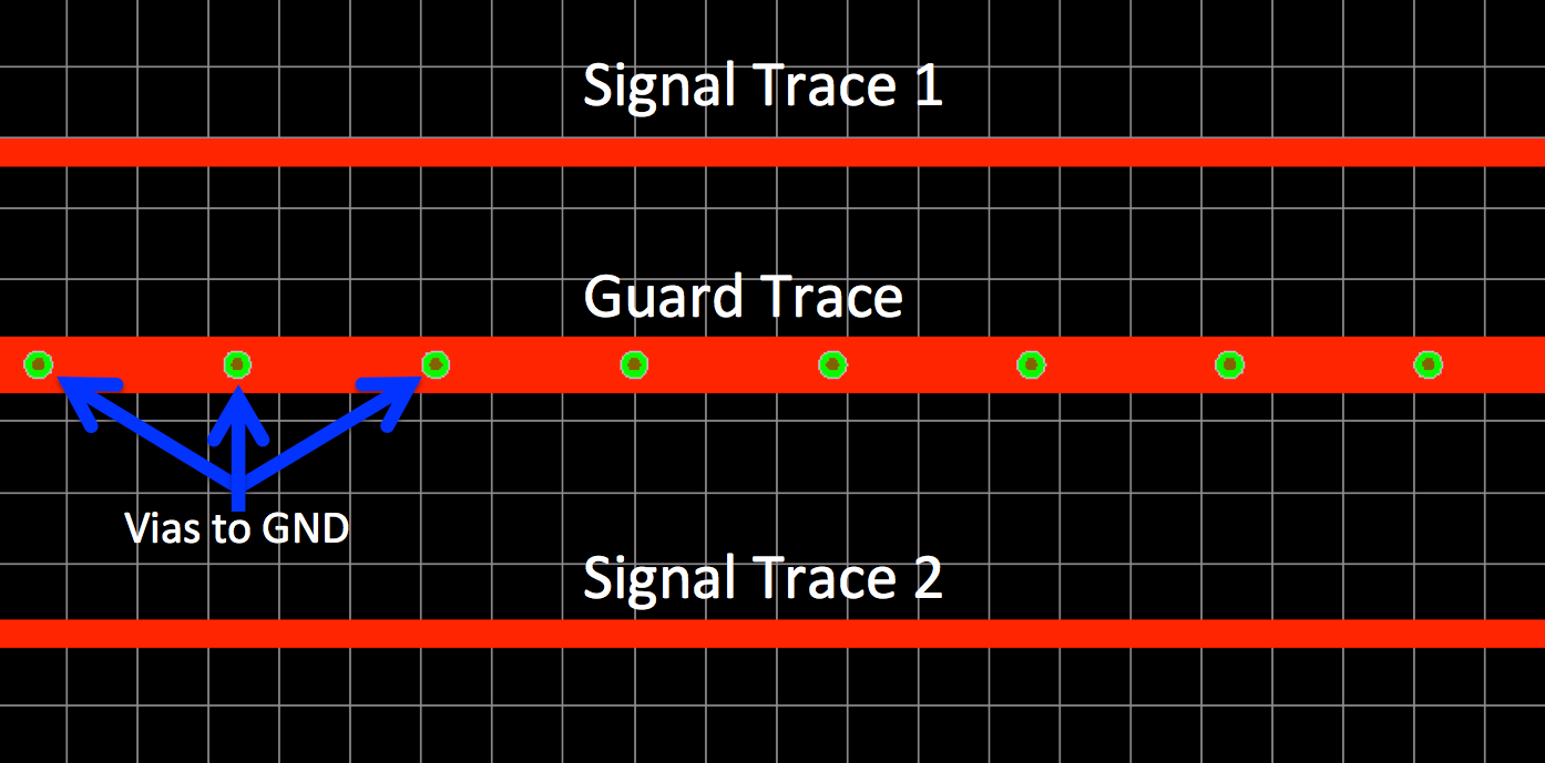
- Isolate CAN Traces: Keep CAN bus traces away from high-speed digital signals or power lines to prevent crosstalk. If necessary, use guard traces or vias to shield the CAN lines.
Following these guidelines will help maintain the integrity of your CAN bus signals, which is crucial for the high-speed data rates (up to 1 Mbps for classic CAN or 5 Mbps for CAN FD) required in autonomous vehicle systems.
Automotive CAN Transceiver Selection: Choosing the Right Component
Selecting the right CAN transceiver is a pivotal step in designing your autonomous vehicle control PCB. The transceiver acts as the interface between the CAN controller and the physical bus, translating digital signals into differential signals and vice versa. Here are key factors to consider during automotive CAN transceiver selection:
- Speed Compatibility: Ensure the transceiver supports the data rate required for your application. For modern autonomous vehicles, consider transceivers compatible with CAN FD (Flexible Data-rate), which supports speeds up to 5 Mbps compared to 1 Mbps for classic CAN.
- Voltage Range: Automotive systems often operate in a wide voltage range (9V to 32V). Choose a transceiver that can handle these fluctuations and includes built-in protection against overvoltage and transients.
- EMI and ESD Protection: Look for transceivers with robust electromagnetic compatibility (EMC) features and electrostatic discharge (ESD) protection (up to ±8 kV or higher) to withstand the harsh automotive environment.
- Low-Power Modes: For energy efficiency, select a transceiver with standby or sleep modes to reduce power consumption when the system is idle—a critical feature for battery-powered autonomous systems.
- Temperature Range: Automotive-grade transceivers should operate reliably in extreme temperatures, typically from -40°C to 125°C, to ensure performance under varying conditions.
By carefully evaluating these parameters, you can select a transceiver that meets the stringent demands of autonomous vehicle communication, ensuring reliable data transmission even in challenging environments.
CAN Bus Termination Techniques for Signal Stability
Proper termination is essential to prevent signal reflections that can corrupt data on the CAN bus. Without termination, signals can bounce back along the bus, leading to errors and communication failures. Here are proven CAN bus termination techniques to ensure stability:
- Standard Termination: Place a 120-ohm resistor at each end of the CAN bus network (not at every node). This matches the characteristic impedance of the bus and absorbs signal energy, preventing reflections. For a typical network, use two 120-ohm resistors—one at the start and one at the end of the bus.
- Split Termination: For improved EMI performance, use a split termination approach. Instead of a single 120-ohm resistor, use two 60-ohm resistors in series with a capacitor (typically 4.7 nF to 10 nF) connected between their midpoint and ground. This configuration helps filter out common-mode noise while maintaining the effective 120-ohm termination.
- Stub Length Consideration: Keep stub lengths (connections from the main bus to individual nodes) as short as possible, ideally less than 0.3 meters at 1 Mbps. Long stubs can cause signal reflections, so route the bus in a daisy-chain topology rather than a star configuration.
Implementing these termination techniques will stabilize your CAN bus signals, ensuring error-free communication across the network. This is especially important in autonomous vehicles, where even minor data errors can have significant consequences.
Ensuring CAN Bus Signal Integrity in Automotive Environments
Maintaining CAN bus signal integrity is a top priority when designing PCBs for autonomous vehicles. Poor signal quality can lead to data errors, communication delays, or complete system failures. Here are essential strategies to ensure signal integrity:
- Differential Pair Routing: Route CANH and CANL as a closely coupled differential pair to minimize noise pickup. Maintain equal trace lengths for both lines to avoid skew, which can distort the differential signal.
- Noise Mitigation: Use ferrite beads or common-mode chokes near the CAN transceiver to filter out high-frequency noise. Additionally, place transient voltage suppression (TVS) diodes near the bus connectors to protect against voltage spikes.
- Connector Placement: Position CAN bus connectors close to the termination resistors to reduce stub effects. Avoid placing connectors in the middle of the bus, as this can introduce reflections.
- Signal Testing: After PCB fabrication, use an oscilloscope to verify signal integrity. Check for clean, square waveforms on CANH and CANL with minimal overshoot or ringing. The differential voltage should typically be around 2V during dominant states and 0V during recessive states.
By prioritizing signal integrity, you can build a CAN bus system that performs reliably under the demanding conditions of autonomous driving, where electromagnetic interference and voltage transients are common.
Automotive Network PCB Design: Best Practices for Autonomous Vehicles
Designing a PCB for an automotive network in autonomous vehicles goes beyond just CAN bus implementation. It involves integrating multiple communication protocols, ensuring scalability, and meeting strict safety standards. Here are best practices for automotive network PCB design:
- Modular Design: Create a modular PCB layout that allows for easy integration of additional communication buses like LIN, FlexRay, or Ethernet (for higher bandwidth needs). This ensures your design can adapt to future upgrades in autonomous systems.
- Power Management: Include robust power supply circuits with filtering to provide clean, stable voltage to CAN transceivers and other components. Use decoupling capacitors (e.g., 0.1 μF and 10 μF) near ICs to reduce noise.
- Thermal Management: Account for heat dissipation in high-density automotive PCBs. Place thermal vias under high-power components and ensure adequate airflow or heat sinks to prevent overheating, especially in enclosed vehicle environments.
- Safety Standards Compliance: Design your PCB to meet automotive safety standards like ISO 26262 (Functional Safety). Implement redundant communication paths or fail-safe mechanisms to ensure system reliability in case of CAN bus failure.
- Compact Layout: Optimize board space by using surface-mount components and multi-layer PCBs. This reduces the footprint while allowing for complex routing and additional features like diagnostics or monitoring circuits.
Adhering to these practices will help you create a PCB that not only supports CAN bus communication but also meets the broader requirements of an autonomous vehicle’s control system, ensuring long-term reliability and performance.
Challenges and Solutions in CAN Bus Implementation for Autonomous Vehicles
Implementing CAN bus on an autonomous vehicle control PCB comes with unique challenges. Addressing these issues proactively can save time and prevent costly redesigns. Here are common challenges and their solutions:
- High Data Traffic: Autonomous vehicles generate massive amounts of data, which can overload a classic CAN bus. Solution: Use CAN FD for higher data rates or integrate Ethernet for backbone communication while reserving CAN for critical control systems.
- EMI Interference: The vehicle environment is prone to EMI from motors, inverters, and other electronics. Solution: Implement shielding, proper grounding, and split termination to minimize noise impact on CAN signals.
- Complex Network Topology: Managing multiple ECUs and long bus lengths can introduce signal delays. Solution: Limit bus length to 40 meters at 1 Mbps and use repeaters or gateways for larger networks.
- Power Fluctuations: Voltage transients from engine start-stop systems can disrupt CAN communication. Solution: Use transceivers with wide input voltage ranges and add protective components like TVS diodes.
By anticipating these challenges and applying the recommended solutions, you can build a CAN bus system that operates flawlessly in the demanding context of autonomous vehicles.
Conclusion: Building Reliable CAN Bus Systems for Autonomous Vehicles
Implementing CAN bus communication on an autonomous vehicle control PCB is a complex but essential task for ensuring reliable, real-time data exchange. By following CAN bus PCB layout guidelines, selecting the right automotive CAN transceiver, applying effective termination techniques, prioritizing signal integrity, and adhering to automotive network PCB design best practices, you can create a robust system that meets the high standards of autonomous driving technology.
At ALLPCB, we understand the intricacies of designing PCBs for cutting-edge applications like autonomous vehicles. Our expertise in high-quality PCB manufacturing and assembly can help bring your CAN bus designs to life with precision and reliability. Whether you're optimizing for signal integrity or scaling up for production, we’re here to support your journey in automotive innovation.
With the right approach and attention to detail, your CAN bus implementation will contribute to safer, smarter, and more efficient autonomous vehicles. Start applying these guidelines today to stay ahead in the rapidly advancing field of automotive electronics.
 ALLPCB


