 ALLPCB


In the fast-evolving world of automotive technology, radar sensors play a critical role in ensuring safety and enabling advanced driver assistance systems (ADAS). At the heart of these sensors lies the printed circuit board (PCB), specifically High-Density Interconnect (HDI) PCB design, which is essential for meeting the demanding requirements of automotive radar. If you're searching for insights on automotive radar PCB design, HDI PCB, microvia technology, high-frequency PCB materials, or signal integrity for radar, you're in the right place. This blog will dive deep into how HDI PCB design powers automotive radar sensors and why it's a game-changer in the industry.
At ALLPCB, we understand the challenges engineers face when designing PCBs for high-performance applications like automotive radar. This comprehensive guide will walk you through the key aspects of HDI PCB design, from material selection to maintaining signal integrity, ensuring your designs meet the strict standards of modern automotive systems.
What is HDI PCB and Why is it Crucial for Automotive Radar?
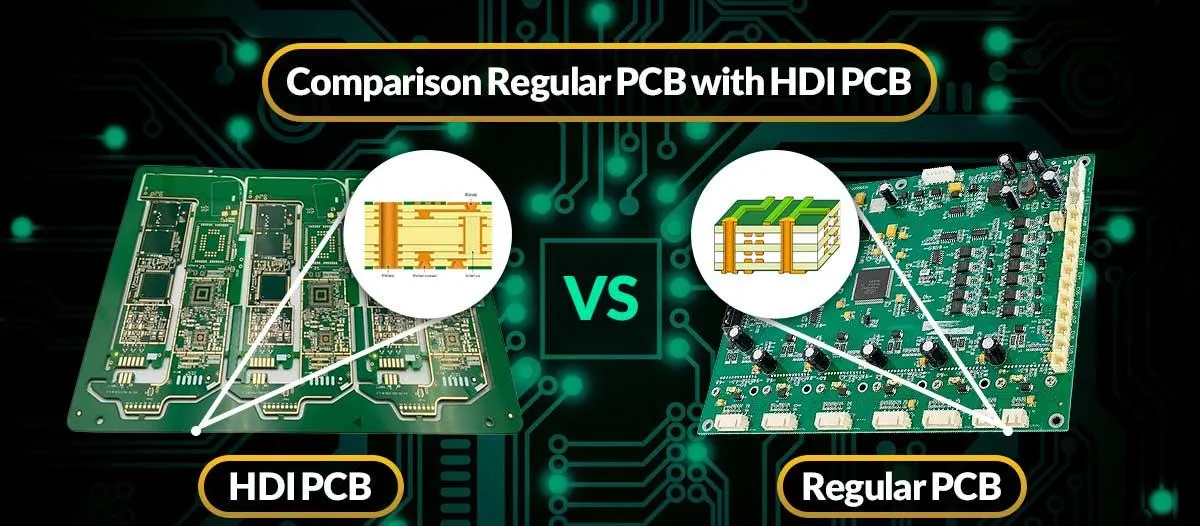
High-Density Interconnect (HDI) PCB is a type of circuit board that uses advanced manufacturing techniques to pack more components into a smaller space. Unlike traditional PCBs, HDI boards feature finer lines, smaller vias, and higher connection pad density. This allows for compact, lightweight designs without sacrificing performance—a perfect fit for automotive radar sensors where space is limited, and precision is non-negotiable.
Automotive radar sensors, used in features like adaptive cruise control and collision avoidance, operate at high frequencies, often in the 24 GHz to 77 GHz range. These frequencies demand PCBs that can handle fast signal transmission while minimizing interference and loss. HDI PCB design addresses these needs by enabling tighter routing, reducing signal path lengths, and improving overall electrical performance.
Key Features of HDI PCB Design for Automotive Radar
HDI PCBs are not a one-size-fits-all solution. When tailored for automotive radar, several specific features make them stand out. Let's explore these in detail.
1. Microvia Technology for Compact Designs
Microvia technology is a cornerstone of HDI PCB design. Microvias are tiny holes, often less than 150 micrometers in diameter, that connect different layers of the PCB. Unlike traditional through-hole vias, microvias save space and allow for denser layouts, which is critical in automotive radar sensors where every millimeter counts.
In radar applications, microvias help reduce parasitic capacitance and inductance, which can degrade high-frequency signals. By using laser-drilled microvias, designers can achieve precise connections between layers, ensuring the board performs reliably even at frequencies as high as 77 GHz.
2. High-Frequency PCB Materials for Optimal Performance
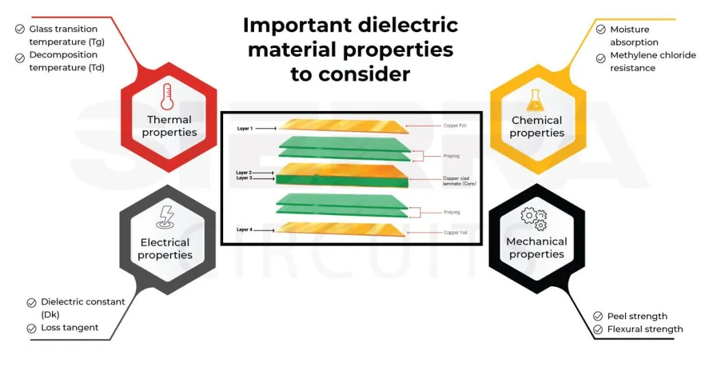
The choice of materials is vital in automotive radar PCB design. Standard FR4 materials, commonly used in low-frequency applications, often fail to meet the needs of high-frequency radar systems due to their higher dielectric loss. Instead, advanced high-frequency PCB materials like PTFE (Polytetrafluoroethylene) or ceramic-filled laminates are preferred.
These materials offer a low dielectric constant (Dk), typically between 2.2 and 3.5, and a low dissipation factor (Df), often below 0.002, which minimizes signal loss at high frequencies. For instance, a radar sensor operating at 77 GHz requires a material with stable Dk to maintain consistent impedance, often targeted at 50 ohms for transmission lines. Using the right material ensures that the radar signal remains strong and accurate over long distances.
3. Signal Integrity for Radar Applications
Signal integrity is the backbone of any radar system. Poor signal integrity can lead to data errors, reduced range, or inaccurate detection—issues that are unacceptable in automotive safety systems. HDI PCB design plays a pivotal role in maintaining signal integrity for radar by minimizing crosstalk, impedance mismatches, and electromagnetic interference (EMI).
For example, in a 77 GHz radar system, signal speeds can reach up to 50% of the speed of light in a vacuum due to the dielectric properties of the PCB material. Any mismatch in impedance, even as small as 5 ohms, can cause reflections and degrade performance. HDI PCBs combat this by allowing precise control over trace widths and spacing, often as narrow as 3 mils (0.076 mm), to maintain consistent impedance throughout the signal path.
Additionally, HDI designs often incorporate ground planes and shielding to reduce EMI, ensuring that the radar sensor can detect objects accurately, even in noisy environments like busy highways.
Benefits of HDI PCB in Automotive Radar Sensors
Now that we've covered the key features, let's look at the tangible benefits HDI PCB brings to automotive radar systems. These advantages make it a preferred choice for engineers working on cutting-edge ADAS solutions.
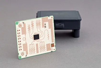
1. Miniaturization for Space-Constrained Applications
Automotive radar sensors are often integrated into tight spaces, such as behind bumpers or within side mirrors. HDI PCBs enable miniaturization by stacking multiple layers—sometimes up to 12 or more—in a compact footprint. This high-density approach reduces the overall size of the radar module while maintaining or even enhancing functionality.
2. Enhanced Reliability in Harsh Conditions
Automotive environments are tough, with temperature swings from -40°C to 85°C, vibrations, and exposure to moisture. HDI PCBs are built to withstand these conditions. Their advanced manufacturing processes, including the use of robust materials and precise soldering techniques, ensure long-term reliability, which is critical for safety systems that must operate flawlessly for years.
3. Improved Electrical Performance
The shorter signal paths and reduced parasitic effects in HDI PCBs lead to better electrical performance. This is especially important for automotive radar, where timing accuracy directly impacts the system's ability to measure distances. For instance, a delay of just 1 nanosecond in signal transmission can translate to a measurement error of about 15 cm, which could be the difference between detecting a pedestrian or missing them entirely.
Design Considerations for HDI PCB in Automotive Radar
Designing an HDI PCB for automotive radar is no simple task. It requires careful planning and attention to detail to meet performance, cost, and manufacturing constraints. Below are some critical considerations for engineers.
1. Layer Stackup and Routing
A typical HDI PCB for radar might include 6 to 12 layers, with a mix of signal, ground, and power planes. The stackup must be designed to isolate high-frequency signals from noise sources. For instance, placing a ground plane between signal layers can reduce crosstalk by up to 20 dB, significantly improving signal quality.
Routing is equally important. High-frequency signals should follow straight, short paths to minimize loss. Bends in traces should be avoided or kept at 45-degree angles to prevent signal reflections. Tools for simulation and impedance calculation are often used to ensure the design meets the target impedance, usually around 50 ohms for radar applications.
2. Thermal Management
Radar sensors generate heat, especially when processing high-frequency signals continuously. HDI PCBs must be designed with thermal vias and heat dissipation paths to prevent overheating. For example, thermal vias with a diameter of 0.3 mm can be placed near high-power components to transfer heat to a copper ground plane, keeping temperatures within safe limits.
3. Compliance with Automotive Standards
Automotive radar systems must comply with strict industry standards like ISO 26262 for functional safety and AEC-Q100 for component reliability. HDI PCB designs need to account for these requirements from the start, incorporating redundancy and fail-safe mechanisms to ensure the system remains operational even under fault conditions.
Challenges in HDI PCB Design for Automotive Radar
While HDI PCBs offer numerous advantages, they also come with challenges that engineers must address during the design and manufacturing process.
1. Manufacturing Complexity
The use of microvias and fine-pitch components increases the complexity of manufacturing HDI PCBs. Laser drilling for microvias, for instance, requires precision equipment and can drive up costs. Additionally, ensuring uniform plating inside microvias to avoid signal discontinuities is a technical hurdle that demands expertise.
2. Cost Considerations
HDI PCBs are generally more expensive than traditional boards due to the advanced materials and processes involved. For automotive applications, where cost control is critical, engineers must balance performance with affordability, often by optimizing the number of layers or selecting cost-effective high-frequency materials without compromising quality.
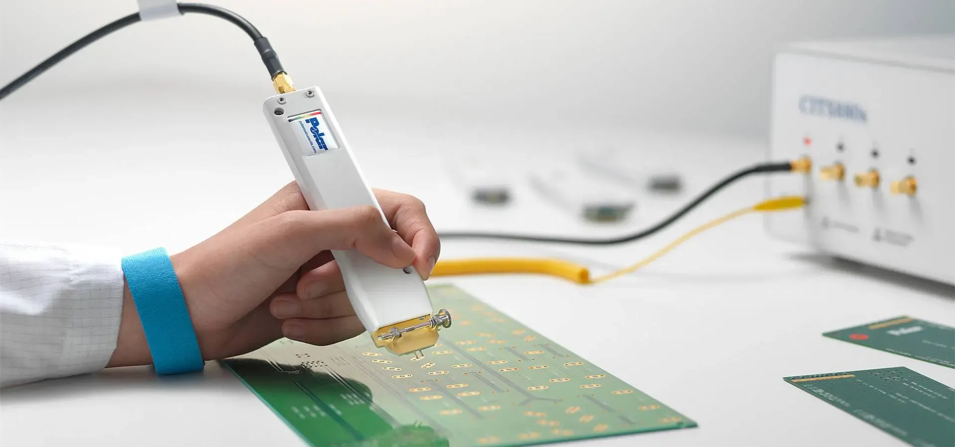
3. Testing and Validation
Validating an HDI PCB for radar applications involves rigorous testing to ensure signal integrity and performance under real-world conditions. High-frequency testing equipment, capable of measuring parameters like return loss and insertion loss at 77 GHz, is essential but can be costly and time-consuming to implement.
How ALLPCB Supports HDI PCB Design for Automotive Radar
At ALLPCB, we specialize in providing high-quality HDI PCB solutions tailored to the unique needs of automotive radar systems. Our advanced manufacturing capabilities allow us to produce boards with microvias as small as 0.1 mm and trace widths down to 3 mils, ensuring your designs achieve the density and precision required for high-frequency applications.
We also offer a wide range of high-frequency materials with low Dk and Df values to minimize signal loss and maintain impedance control. Our team of experts works closely with engineers to optimize layer stackups, thermal management, and routing, ensuring your PCB meets both performance and cost goals. With a commitment to meeting automotive industry standards, we provide reliable solutions that power the next generation of ADAS technologies.
Future Trends in HDI PCB Design for Automotive Radar
The automotive industry is moving toward greater autonomy, with radar sensors playing a central role in enabling Level 4 and Level 5 autonomous vehicles. As a result, HDI PCB design is expected to evolve in several ways:
- Higher Frequency Bands: Future radar systems may operate at frequencies beyond 77 GHz, pushing the boundaries of material science and PCB design to achieve even lower signal loss.
- Integration with Other Sensors: HDI PCBs will need to support multi-sensor fusion, combining radar with LiDAR and cameras on a single board for enhanced perception.
- Cost Reduction: Advances in manufacturing techniques are likely to make HDI PCBs more affordable, enabling their adoption in a wider range of vehicles, from luxury to economy models.
Conclusion
HDI PCB design is a critical enabler of automotive radar sensors, providing the compact size, high performance, and reliability needed for modern safety systems. By leveraging microvia technology, high-frequency PCB materials, and precise signal integrity practices, engineers can create radar modules that meet the stringent demands of ADAS applications. Despite the challenges of manufacturing complexity and cost, the benefits of HDI PCBs far outweigh the drawbacks, making them indispensable in the automotive industry.
At ALLPCB, we're dedicated to helping you navigate the complexities of HDI PCB design for automotive radar. Whether you're optimizing for signal integrity or tackling thermal management, our expertise and cutting-edge manufacturing capabilities ensure your project succeeds. As the automotive world continues to innovate, HDI PCB technology will remain at the forefront, driving safer and smarter vehicles for the future.


