 ALLPCB


Are you a hobbyist or beginner looking to dive into DIY PCB design for a ventilator project? This comprehensive guide will walk you through the essentials of creating a printed circuit board (PCB) for a ventilator, from understanding the basics to using online PCB design tools. Whether you're exploring PCB design as a hobby or tackling a meaningful project like a ventilator, we’ve got you covered with actionable steps and tips. Let’s get started on your journey to mastering DIY PCB design with this beginner’s guide tailored for hobbyists.
Why Build a DIY Ventilator PCB?
Designing a PCB for a ventilator as a DIY project can be both a learning experience and a way to contribute to innovative solutions. Ventilators are critical medical devices that assist with breathing, and while professional-grade ventilators are complex, a simplified DIY version can serve as an educational tool or prototype for understanding the underlying electronics. This guide focuses on the PCB design aspect, providing hobbyists with a starting point to explore this challenging yet rewarding field.
Understanding the Basics of PCB Design for Beginners
Before diving into the specifics of a ventilator PCB, let’s cover the fundamentals of PCB design. A PCB is a board that connects electronic components using conductive tracks, pads, and other features. It’s the backbone of most electronic devices, including ventilators, which rely on precise control of sensors, motors, and power systems.
For beginners, PCB design might seem daunting, but it breaks down into a few key steps:
- Schematic Design: This is like a blueprint of your circuit, showing how components connect.
- Component Placement: Arranging components on the board to minimize interference and optimize space.
- Routing: Drawing the conductive paths (traces) that connect components.
- Testing and Validation: Ensuring the design works as intended before manufacturing.
In a ventilator, the PCB might control airflow sensors, pressure regulators, and alarms, requiring careful attention to signal integrity and power management. For instance, signal speeds in digital circuits can reach up to 100 MHz in some control systems, and impedance mismatches can cause delays or noise. Keeping traces short and using ground planes can help maintain signal integrity.

Key Components of a DIY Ventilator PCB
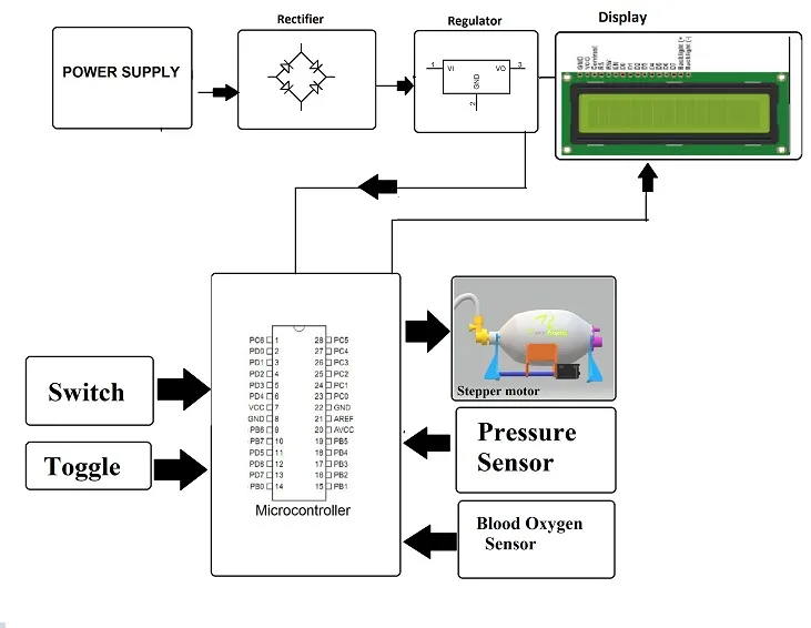
A basic DIY ventilator circuit typically includes components that monitor and control airflow and pressure. While this guide doesn’t cover medical-grade designs, understanding these elements can help hobbyists build educational prototypes. Here are some common components you might include on your PCB:
- Microcontroller: The brain of the system, managing inputs from sensors and controlling outputs like motors. A typical choice might handle 5V logic levels with a clock speed of 16 MHz.
- Sensors: Pressure and airflow sensors to monitor breathing parameters. These often output analog signals in the range of 0-5V.
- Motor Drivers: To control valves or pumps, often requiring current handling of up to 2A at 12V.
- Power Supply Circuit: To provide stable voltage, such as 5V or 12V, with current ratings matching component needs.
- LEDs and Alarms: For status indicators or alerts, typically drawing 20mA per LED.
Each component needs to be carefully placed on the PCB to avoid interference. For example, high-current motor drivers should be kept away from sensitive analog sensor circuits to prevent noise.
Step-by-Step Guide to DIY Ventilator PCB Design
Now, let’s walk through the process of designing a PCB for a basic ventilator circuit. This beginner’s guide is tailored for hobbyists, focusing on simplicity and accessibility.
Step 1: Define Your Requirements
Start by listing what your ventilator prototype needs to do. For a basic educational model, you might aim to control a small air pump and monitor pressure with a sensor. Define input voltage (e.g., 12V DC), expected current draw (e.g., 1A total), and key functions like pump on/off control.
Step 2: Create a Schematic
Using PCB design software, draw a schematic of your circuit. Place your microcontroller at the center, connect sensors to analog input pins, and link motor drivers to digital output pins. Include power supply components like voltage regulators to step down 12V to 5V for logic circuits. Ensure all connections follow the datasheets of your chosen components for accurate pin assignments.
Step 3: Choose Components and Footprints
Select components with footprints that match your design software’s library. For instance, a microcontroller might come in a DIP package for easy soldering by hobbyists, with a footprint size of 0.3 inches per pin spacing. Double-check voltage and current ratings to avoid mismatches.
Step 4: Design the PCB Layout
Move to the layout editor in your software. Place components logically—group power-related parts together and keep sensitive signal traces short. Use a ground plane to reduce noise, especially around sensor circuits where signal accuracy is critical. Route traces with a minimum width of 0.01 inches for low-current signals and wider (e.g., 0.05 inches) for power lines carrying up to 1A.
Step 5: Validate and Export
Run design rule checks (DRC) in your software to spot errors like unconnected pins or overlapping traces. Once validated, export your design files in a standard format like Gerber, which manufacturers use to produce the PCB.

Best PCB Software for Hobbyists and Beginners
For hobbyists diving into online PCB design, choosing the right software is crucial. Many tools are beginner-friendly, offering free versions with powerful features. Here are some options to consider for your DIY ventilator PCB project:
- Free Desktop Software: Some programs offer intuitive interfaces with drag-and-drop schematic editors and extensive component libraries. They often support up to 2-layer boards for free, which is sufficient for most hobbyist projects.
- Cloud-Based Design Tools: These allow you to design PCBs online without installing software. They’re ideal for collaboration and often include tutorials for beginners, making them perfect for a first-time ventilator PCB design.
- Open-Source Options: Certain platforms provide free access to schematic and layout editors, with community support for troubleshooting. They’re great for hobbyists on a budget.
Most of these tools include simulation features to test your circuit before manufacturing, helping you catch errors early. For a ventilator project, simulate sensor inputs (e.g., a 2.5V signal representing normal pressure) to ensure your microcontroller responds correctly.
Tips for Successful DIY PCB Design as a Hobbyist
Designing a PCB for a ventilator, even as a prototype, comes with challenges. Here are some practical tips to ensure success:
- Start Simple: Begin with a basic circuit controlling one function, like turning a pump on and off, before adding complexity like sensor feedback.
- Use Reference Designs: Look for open-source ventilator schematics online to understand common layouts and component choices. Adapt these to your needs while ensuring safety.
- Plan for Power: Ventilator circuits may require multiple voltage levels (e.g., 5V for logic, 12V for motors). Include proper decoupling capacitors (e.g., 0.1μF near ICs) to stabilize power.
- Test Incrementally: After manufacturing, test each section of your PCB separately. For example, verify sensor readings match expected values (e.g., 3V for a specific pressure) before connecting the motor driver.
- Prioritize Safety: Remember that ventilators are medical devices. DIY projects should remain educational and not be used in real medical settings without expert validation.
Common Challenges in DIY Ventilator PCB Design
As a beginner, you might face hurdles while designing your PCB. Here’s how to tackle some common issues:
- Signal Noise: Sensors in ventilators can pick up interference from nearby power traces. Use separate ground planes for analog and digital sections to minimize this. Keep trace lengths under 2 inches for high-frequency signals if possible.
- Component Heat: Motor drivers can generate heat when handling currents above 1A. Add heat sinks or ensure adequate board spacing (e.g., 0.5 inches around high-power components).
- Software Learning Curve: If online PCB design tools feel complex, start with their built-in tutorials or community forums for guidance. Spend time practicing with smaller projects first.
Manufacturing Your DIY Ventilator PCB
Once your design is ready, it’s time to manufacture the PCB. Many services offer affordable options for hobbyists, producing small batches of boards with quick turnaround times. Here’s how to proceed:
- Export Gerber Files: These are the industry-standard files for PCB production. Ensure all layers (copper, silkscreen, solder mask) are included.
- Choose Specifications: Opt for a 2-layer board with 1.6mm thickness and standard FR4 material for cost-effectiveness. Specify trace width and spacing as per your design (e.g., 0.01-inch minimum clearance).
- Order and Assemble: After receiving your boards, solder components manually if you’re a hobbyist, or use assembly services for precision. Test the board with a multimeter to confirm connections match your schematic.
At ALLPCB, we support hobbyists and beginners with resources and services to bring your DIY ventilator PCB designs to life. Our platform ensures high-quality manufacturing tailored to your specifications, helping you focus on innovation.
Conclusion: Start Your DIY PCB Design Journey Today
Designing a PCB for a ventilator as a DIY project is an excellent way for hobbyists to learn about electronics and PCB design. This beginner’s guide has walked you through the basics, from understanding key components to using online PCB design tools and overcoming common challenges. By starting small, leveraging free software, and focusing on safety, you can create a functional prototype that enhances your skills.
Remember, every expert started as a beginner. Take your first step into DIY PCB design with confidence, knowing that resources and communities are available to support you. Whether it’s for a ventilator project or another idea, the skills you build today will open doors to endless possibilities in electronics.


