 ALLPCB


Are you a tech enthusiast or hobbyist looking to create a custom e-reader from the ground up? Building your own DIY E-Reader PCB project is an exciting and rewarding endeavor. Whether you're exploring a custom E-Reader PCB design or diving into an open source E-Reader PCB, this guide will walk you through the process step by step. We'll cover everything from understanding the basics to designing a hobbyist E-Reader PCB and finding an E-Reader PCB schematic. Let’s get started on crafting a device that’s uniquely yours!
Why Build a DIY E-Reader PCB?
Creating your own e-reader offers a sense of accomplishment and allows you to tailor the device to your specific needs. Commercial e-readers can be expensive and often come with limitations on customization or file formats. With a DIY E-Reader PCB project, you gain full control over hardware and software, ensuring the device works exactly as you want. Plus, it’s a fantastic learning experience for anyone interested in electronics and printed circuit board design.
Beyond personal satisfaction, building a custom E-Reader PCB design can be cost-effective if you source components wisely. It also opens doors to experimenting with open source E-Reader PCB designs, where communities share schematics and code to help you get started. Whether you’re a seasoned engineer or a curious hobbyist, this project offers a hands-on way to dive into the world of embedded systems and display technology.
Understanding the Basics of an E-Reader PCB
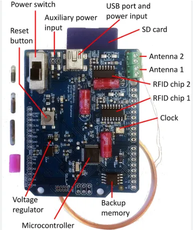
Before jumping into the design process, let’s break down what an E-Reader PCB is and the core components you’ll need. A printed circuit board (PCB) is the backbone of any electronic device, connecting all components like the brain, display, and power supply. For a hobbyist E-Reader PCB, the goal is to create a compact, efficient layout that supports reading digital books with minimal power consumption.
The key components of an e-reader include:
- Microcontroller: This acts as the brain, processing data and managing user inputs. Popular choices include microcontrollers with low power consumption, often running at speeds of 80-240 MHz.
- E Ink Display: Known for low power usage, E Ink displays are ideal for e-readers. They typically range from 4.2 to 7.5 inches with resolutions like 800x600 pixels.
- Memory: You’ll need storage for e-books, often via an SD card slot or onboard flash memory (e.g., 8-16 GB).
- Power Management: A battery (like a 3.7V Li-Po) and a charging circuit are crucial for portability.
- User Interface: Buttons or a touchscreen for navigation.
Understanding these elements helps in planning your E-Reader PCB schematic, ensuring all parts work together seamlessly.
Step 1: Planning Your DIY E-Reader PCB Project
Every successful project starts with a solid plan. Define your goals for the e-reader. Are you focusing on a minimalist design for basic reading, or do you want advanced features like Wi-Fi for downloading books? Your objectives will shape the complexity of your custom E-Reader PCB design.
Next, decide on the display size and type. A 6-inch E Ink display with a resolution of 1024x758 pixels offers a good balance between readability and power efficiency. Also, consider power needs—E Ink displays consume around 0.5-1 mW during page refreshes and almost nothing when static, making them ideal for long battery life.
Finally, choose between designing your PCB from scratch or using an open source E-Reader PCB as a starting point. Open source designs often come with community support, detailed schematics, and software, saving you time.
Step 2: Gathering Components for Your Hobbyist E-Reader PCB
Once your plan is ready, it’s time to source components. Here’s a detailed list to guide your DIY E-Reader PCB project:
- Microcontroller: Look for a low-power option with enough processing power (e.g., 32-bit processors with 128-256 KB RAM).
- E Ink Display: Choose a display with a compatible controller. A 4.2-inch display might cost around $20-30 and draw minimal power.
- Power Supply: A 3.7V, 1000mAh Li-Po battery can provide days of usage due to E Ink’s efficiency.
- Storage: An SD card module supporting up to 32 GB is affordable and easy to integrate.
- Connectors and Buttons: Simple tactile buttons for page turning and menu navigation work well.
Budget around $50-100 for components, depending on the features you want. Buying in bulk or from wholesale suppliers can reduce costs significantly.
Step 3: Designing Your E-Reader PCB Schematic
The heart of your project lies in the E-Reader PCB schematic. This blueprint maps out how components connect electrically. If you’re new to PCB design, start with free software tools that offer schematic editors and layout designers. These tools often include libraries for common components like microcontrollers and display drivers.
Key tips for designing your schematic:
- Power Lines: Ensure stable voltage delivery, typically 3.3V or 5V, depending on your components. Include capacitors (e.g., 10 μF) near power pins to filter noise.
- Signal Integrity: Keep data lines short to minimize interference, especially for SPI or I2C communication with the display, which operates at speeds up to 4 MHz.
- Ground Plane: Use a solid ground plane to reduce electromagnetic interference.
If designing from scratch feels daunting, explore open source E-Reader PCB designs available online. Many hobbyists share their schematics and layouts, which you can modify to fit your needs. Just ensure you review the design for compatibility with your chosen components.
Step 4: Creating the PCB Layout
After finalizing the schematic, move to the PCB layout phase. This step involves placing components on the board and routing traces to connect them. Aim for a compact design to save space and reduce manufacturing costs. A two-layer board (top and bottom) is often sufficient for a hobbyist E-Reader PCB, measuring around 100mm x 80mm for a 6-inch display.
Design tips for the layout:
- Place the microcontroller centrally to minimize trace lengths to other components.
- Position the E Ink display connector near the edge for easy assembly.
- Route power traces wider (e.g., 20-30 mil) than signal traces (8-10 mil) to handle current without overheating.
Double-check your layout for errors like overlapping traces or unconnected pins before moving to production.
Step 5: Manufacturing Your DIY E-Reader PCB
With your design ready, it’s time to manufacture the PCB. Partner with a reliable fabrication service to turn your digital design into a physical board. At ALLPCB, we offer high-quality manufacturing with quick turnaround times, ensuring your DIY E-Reader PCB project comes to life without hassle. Upload your Gerber files—standard output from most design software—and select specifications like board thickness (1.6mm is common) and copper weight (1 oz is standard).
Costs for a small batch of 5-10 boards can range from $10-30, depending on size and complexity. Once manufactured, inspect the boards for defects like misaligned holes or broken traces before soldering components.
Step 6: Assembling and Soldering Components
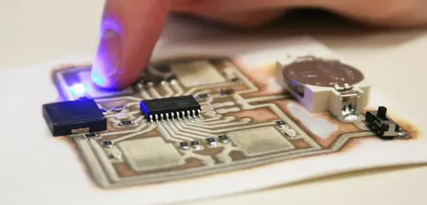
Assembly involves soldering components onto your PCB. If you’re new to soldering, practice on scrap boards first to avoid damaging your e-reader PCB. Use a soldering iron with a fine tip (25-30W) and lead-free solder for safety.
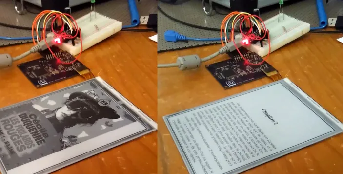
Start with low-profile components like resistors and capacitors, then move to larger ones like the microcontroller and connectors. Ensure proper alignment, especially for the E Ink display connector, as misalignment can cause display issues. After soldering, test continuity with a multimeter to confirm there are no short circuits.
Step 7: Programming Your E-Reader
With hardware assembled, it’s time to program the microcontroller. Use open source firmware or write your own code to handle e-book rendering, button inputs, and power management. Common programming environments support languages like C or Python, depending on your microcontroller.
Basic firmware should:
- Read e-book files (e.g., EPUB, PDF) from storage.
- Drive the E Ink display to render text, refreshing at a rate of 1-2 seconds per page turn.
- Manage battery usage to maximize runtime.
Many open source E-Reader PCB projects provide ready-to-use code, which you can tweak for custom features like font size adjustments or backlight control.
Step 8: Testing and Troubleshooting
Testing ensures your e-reader functions as intended. Power it on and check if the display initializes correctly. Load a sample e-book and verify that pages turn smoothly without flickering. If issues arise, troubleshoot systematically:
- Display Problems: Check connections and ensure the display driver is correctly programmed.
- Power Issues: Measure voltage at key points with a multimeter; it should match component requirements (e.g., 3.3V).
- Button Failures: Inspect solder joints and test for continuity.
Patience is key—debugging can take time but ensures a reliable device.
Tips for Enhancing Your Custom E-Reader PCB Design
Once your basic e-reader works, consider upgrades to enhance functionality:
- Add a backlight circuit with LEDs (drawing 20-50 mA) for night reading.
- Integrate Wi-Fi or Bluetooth modules for wireless book downloads, ensuring the module operates at 2.4 GHz for compatibility.
- Design a custom enclosure using 3D printing to protect the PCB and give it a polished look.
These additions can elevate your hobbyist E-Reader PCB into a device rivaling commercial products.
Challenges and Solutions in DIY E-Reader Projects
Building an e-reader isn’t without challenges. Component compatibility can be an issue—E Ink displays often require specific drivers, so double-check datasheets before purchasing. Power management is another hurdle; inefficient designs can drain batteries quickly. Use low-dropout regulators (LDOs) with quiescent currents below 50 μA to optimize efficiency.
Software bugs can also frustrate progress. Leverage online forums and communities for support, especially if using open source E-Reader PCB designs. Shared solutions and updates can save hours of debugging.
Conclusion: Start Your DIY E-Reader PCB Journey Today
Building a DIY E-Reader PCB is a fulfilling project that combines creativity, technical skill, and problem-solving. From planning your custom E-Reader PCB design to assembling and programming, each step brings you closer to a personalized reading device. Whether you’re a beginner exploring a hobbyist E-Reader PCB or an expert tweaking an open source E-Reader PCB, the process offers endless learning opportunities.
Ready to start? Gather your components, sketch out an E-Reader PCB schematic, and bring your vision to life with high-quality manufacturing support from ALLPCB. Dive into this hands-on project and enjoy the satisfaction of reading e-books on a device you built from scratch!


