ALLPCB


If you're working on Raspberry Pi projects and wondering how to choose the right trace width for your PCB design, you're in the right place. Trace width is crucial for ensuring your circuit board can handle the current, maintain signal integrity, and avoid overheating. For Raspberry Pi projects, which often involve a mix of power and signal traces, a general guideline is to use wider traces (like 20-30 mils) for power lines carrying higher currents (e.g., 500mA to 1A for a 5V supply) and narrower traces (6-10 mils) for low-current signal lines. However, the exact width depends on factors like current, copper thickness, and temperature rise. In this visual guide, we'll dive deep into the specifics of PCB trace width for Raspberry Pi projects, offering practical tips, calculations, and visual aids to help you design reliable and efficient circuit boards.
Why Trace Width Matters in Raspberry Pi Projects
When designing a PCB for Raspberry Pi projects, trace width is one of the most important factors to get right. Traces are the copper pathways on a circuit board that carry electrical signals and power between components. If the trace is too narrow for the current it carries, it can overheat, leading to performance issues or even board failure. On the other hand, overly wide traces can waste valuable board space, making your design less compact and harder to route.
Raspberry Pi projects often involve a mix of power delivery (like 5V or 3.3V lines) and data signals (such as GPIO pins for sensors or communication protocols like I2C and SPI). Each type of trace has different requirements. Power traces need to handle higher currents without excessive voltage drop or heat, while signal traces must minimize interference and maintain signal integrity. Understanding how to calculate and choose the right trace width for these different needs is essential for a successful project.
Understanding the Basics of PCB Trace Width
Trace width refers to the physical width of the copper pathway on a PCB, typically measured in mils (1 mil = 0.001 inches) or millimeters. The width directly affects how much current a trace can carry without overheating. It also influences the trace's resistance and impedance, which are critical for power delivery and signal quality.
For Raspberry Pi projects, trace width selection depends on several factors:
- Current Load: How much current (in amperes) the trace needs to carry. For example, a 5V power line for a Raspberry Pi might need to handle 500mA to 1A, depending on the model and peripherals.
- Copper Thickness: Measured in ounces per square foot (oz/ft2), this determines how much current a trace can carry for a given width. Common thicknesses are 1 oz/ft2 (35 μm) and 2 oz/ft2 (70 μm).
- Temperature Rise: The acceptable increase in temperature (in °C) due to current flow. A 10°C rise is often a safe target for most projects.
- Trace Length: Longer traces have higher resistance, which can cause voltage drops and heat buildup.
- Signal Type: High-speed signals (like HDMI or USB on a Raspberry Pi) may require specific trace widths to match impedance, often around 50 ohms for single-ended signals.
Balancing these factors ensures your PCB operates reliably without wasting space or materials. Let’s explore how to calculate trace width for Raspberry Pi circuit board traces.
How to Calculate Trace Width for Raspberry Pi Projects
Calculating the right trace width involves understanding the current your circuit will carry and the physical properties of your PCB. A common standard for trace width calculation is based on the IPC-2221 guidelines, which provide formulas and charts for determining safe widths based on current, copper thickness, and temperature rise.
Here’s a step-by-step process to calculate trace width:
- Determine the Current: Identify the maximum current your trace will carry. For example, a Raspberry Pi 4 typically draws around 600-800mA at 5V under normal load, but this can spike to 1.2A with heavy peripherals. Check your project’s power requirements for accuracy.
- Choose Copper Thickness: Most hobbyist PCBs use 1 oz/ft2 copper. If you expect higher currents, opt for 2 oz/ft2 for better current-handling capacity.
- Set Temperature Rise: A 10°C rise is a safe starting point for most designs. Higher rises (like 20°C) can be used if heat dissipation isn’t a concern, but they may reduce the board’s lifespan.
- Use a Calculator or Chart: Online tools or IPC-2221 charts can help. For a 1A current on a 1 oz/ft2 copper PCB with a 10°C rise, the recommended trace width is approximately 20-25 mils (0.5-0.6 mm) for external traces. Internal traces (on multilayer boards) may need to be wider due to less heat dissipation.
For signal traces in Raspberry Pi projects, current is usually very low (less than 30mA for GPIO pins), so a minimum width of 6-10 mils is often sufficient. However, for high-speed signals, you might need to match impedance, which requires specific widths based on the PCB stack-up and dielectric material. A typical 50-ohm trace on a standard FR4 board with 1 oz copper might be around 8-12 mils wide, depending on the layer and board thickness.
Trace Width Recommendations for Raspberry Pi Circuit Board Traces
Let’s break down specific recommendations for different types of traces in Raspberry Pi projects. These are general guidelines based on common scenarios and can be adjusted based on your specific design needs.
Power Traces (5V and 3.3V Lines)
- Current: 500mA to 1.2A for 5V lines (depending on Raspberry Pi model and peripherals); 100-300mA for 3.3V lines.
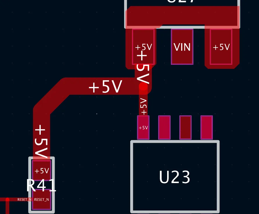
- Width: 20-30 mils for 1 oz copper at 10°C rise. Increase to 40-50 mils for longer traces or higher currents to minimize voltage drop.
- Tip: Use shorter traces for power delivery and place decoupling capacitors near the Raspberry Pi to stabilize voltage.
Ground Traces and Planes
- Current: Ground traces often carry return currents equal to the power traces.
- Width: Match the width of corresponding power traces, or use a ground plane for better current distribution and noise reduction.
- Tip: A solid ground plane under the Raspberry Pi and critical components reduces electromagnetic interference (EMI).
Signal Traces (GPIO, I2C, SPI)
- Current: Typically under 30mA for digital signals.
- Width: 6-10 mils is usually sufficient for low-speed signals. For high-speed signals (e.g., SPI at 50 MHz), calculate width for impedance matching (often 8-12 mils for 50 ohms on FR4).
- Tip: Keep signal traces short and avoid sharp bends to prevent signal reflection and noise.
These values are starting points. Always verify with your PCB design software’s built-in calculators or online tools to ensure accuracy for your specific board setup.
Common Mistakes to Avoid with PCB Trace Width in Raspberry Pi Projects
Even with the right calculations, it’s easy to make mistakes that can affect your PCB’s performance. Here are some pitfalls to watch out for:
- Underestimating Current: Failing to account for peak current draw (e.g., during Raspberry Pi boot-up or with power-hungry peripherals) can lead to overheating traces. Always design for the worst-case scenario.
- Ignoring Voltage Drop: Long, narrow traces can cause significant voltage drops, especially on power lines. For a 5V line carrying 1A over a 100mm trace at 10 mils width, the voltage drop could be 0.1-0.2V, which might affect performance.
- Neglecting Signal Integrity: High-speed signals on Raspberry Pi projects (like USB or HDMI interfaces) require controlled impedance. Incorrect trace width or poor routing can lead to data errors.
- Overloading Small Boards: Hobbyists often cram components onto small PCBs, leaving little room for wide traces. Plan your layout early to allocate space for power traces and ground planes.
Tools and Resources for Designing Raspberry Pi PCBs
Designing a PCB for Raspberry Pi projects doesn’t have to be complicated. Several free and accessible tools can help you calculate trace widths and simulate your design:
- Online Calculators: Many websites offer free trace width calculators that follow industry standards like IPC-2221. Input your current, copper thickness, and temperature rise to get instant recommendations.
- PCB Design Software: Popular software often includes built-in trace width calculators and design rule checks (DRC) to ensure your traces meet current and spacing requirements.
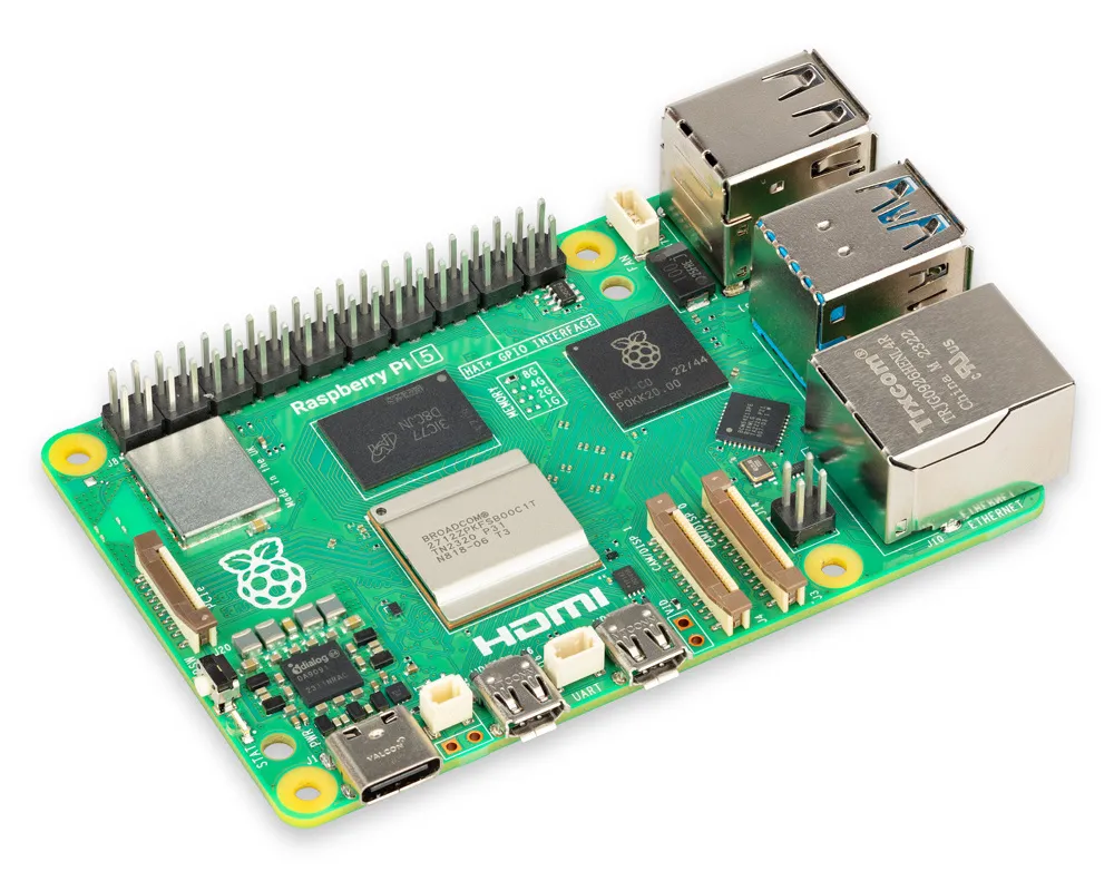
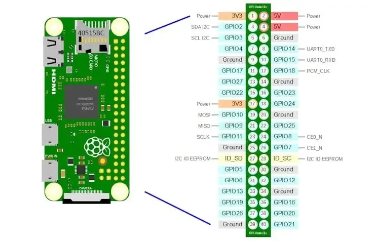
- Raspberry Pi Documentation: Official schematics and hardware guides provide power consumption data and pinout details, helping you estimate current needs for your traces.
Using these tools, you can double-check your calculations and ensure your PCB design is optimized for performance and reliability.
Tips for Optimizing Trace Width in Small Raspberry Pi Projects
Space is often limited in Raspberry Pi projects, especially for compact designs like hats or shields. Here are some tips to optimize trace width without sacrificing performance:
- Use Multilayer Boards: If space is tight, consider a 4-layer PCB. Internal layers can carry power and ground planes, freeing up surface layers for signal traces.
- Prioritize Power Traces: Route power and ground traces first, ensuring they’re wide enough for current demands. Then, fit signal traces around them.
- Minimize Trace Length: Shorter traces reduce resistance and heat buildup, allowing you to use slightly narrower widths without issues.
- Incorporate Vias: For power delivery in tight spaces, use vias to connect to a power plane on another layer, reducing the need for wide surface traces.
These strategies help balance space constraints with the need for safe and effective trace widths.
Conclusion: Building Better Raspberry Pi Projects with Proper Trace Widths
Choosing the right trace width for Raspberry Pi projects is a fundamental step in creating reliable and efficient circuit boards. By understanding your project’s current requirements, calculating trace widths based on copper thickness and temperature rise, and following best practices for power and signal traces, you can avoid common design pitfalls and ensure optimal performance. Whether you’re building a simple sensor module or a complex hat for your Raspberry Pi, proper trace width design will save you time, money, and frustration in the long run.
Start with the guidelines provided in this visual guide—20-30 mils for power traces, 6-10 mils for signals, and adjust based on impedance for high-speed lines. Use online calculators and design tools to refine your numbers, and always prioritize safety by designing for peak currents. With these tips, you’re well on your way to mastering PCB trace width for Raspberry Pi projects and creating boards that are both functional and durable.