 ALLPCB


When it comes to designing printed circuit boards (PCBs) for telecommunication base stations, selecting the right material is critical for ensuring optimal performance, especially in high-frequency applications. The two most commonly considered materials are FR4 and Rogers, each with distinct properties that impact signal integrity, cost, and durability. So, which material should you choose for your telecommunication base station PCB? In short, FR4 is a cost-effective choice for lower-frequency applications, while Rogers materials excel in high-frequency, low-loss environments due to their superior dielectric properties and thermal stability.
In this comprehensive guide, we’ll dive deep into PCB material selection, focusing on high-frequency PCB materials and low-loss PCB materials. We’ll compare FR4 and Rogers to help you make an informed decision for your next project. Whether you’re an engineer or a project manager, this blog will provide actionable insights to ensure your telecommunication base station PCBs meet performance and budget requirements.
Why PCB Material Selection Matters for Telecommunication Base Stations
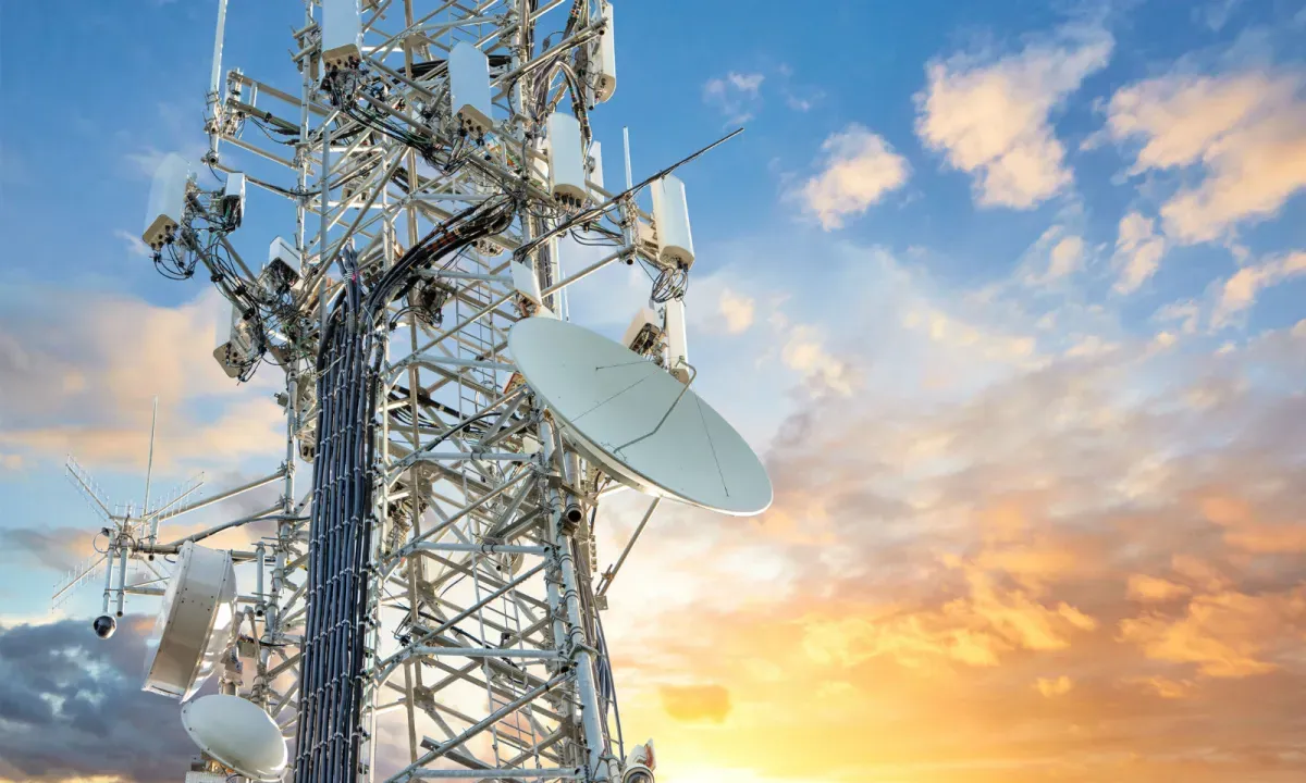
Telecommunication base stations are the backbone of modern communication networks, handling signals for 4G, 5G, and beyond. These systems operate at high frequencies—often in the range of 1 GHz to 6 GHz or higher—where signal integrity, minimal loss, and thermal stability are non-negotiable. The PCB material you choose directly affects how well the board handles these demands.
A poor material choice can lead to signal degradation, increased power consumption, and even system failures. For instance, a material with a high dissipation factor (Df) can cause significant signal loss at high frequencies, impacting the efficiency of data transmission. On the other hand, selecting a material with excellent dielectric properties can ensure reliable performance, even in harsh environmental conditions like extreme temperatures or humidity.
Key Factors in PCB Material Selection for High-Frequency Applications
Before comparing specific materials, let’s explore the key factors to consider when selecting a PCB material for telecommunication base stations:
- Dielectric Constant (Dk): This value indicates how much a material can store electrical energy. A lower Dk is often preferred for high-frequency applications to reduce signal delay.
- Dissipation Factor (Df): This measures signal loss. Low-loss PCB materials have a lower Df, making them ideal for high-frequency signals.
- Thermal Stability: Base stations often operate in varying temperatures. Materials must maintain performance without degrading.
- Cost: Budget constraints play a significant role. Balancing performance with affordability is key.
- Manufacturability: Some materials are harder to process, impacting production time and cost.
With these factors in mind, let’s compare two popular choices for high-frequency PCB materials: FR4 and Rogers.
FR4 PCB: The Cost-Effective Standard
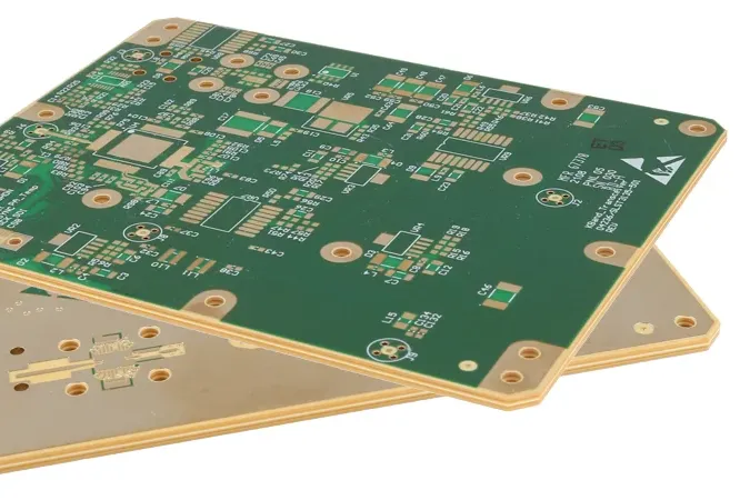
FR4, short for Flame Retardant 4, is a widely used PCB material made of woven glass reinforced with epoxy resin. It’s often the go-to choice for many applications due to its affordability and versatility. But how does it hold up for telecommunication base stations?
Advantages of FR4 PCB
- Cost-Effective: FR4 is significantly cheaper than specialized materials, making it ideal for projects with tight budgets.
- Mechanical Strength: Its rigid structure provides good durability for general use.
- Wide Availability: FR4 is a standard material, easily sourced and supported by most PCB fabrication processes.
Limitations of FR4 in High-Frequency Applications
While FR4 is a reliable choice for many applications, it has notable drawbacks for high-frequency telecommunication systems:
- Higher Dissipation Factor: FR4 typically has a Df of around 0.02, which leads to greater signal loss at frequencies above 1 GHz.
- Dielectric Constant Variability: FR4 has a Dk of about 4.5, but this value can vary with frequency and temperature, affecting impedance stability.
- Thermal Limitations: FR4 can struggle in extreme conditions, with a glass transition temperature (Tg) of around 130-140°C, which may not suffice for high-power base station applications.
For telecommunication base stations operating below 1 GHz, FR4 can be a practical choice. However, as frequencies climb higher—especially in 5G networks—its limitations become more apparent.
Rogers PCB: The High-Performance Choice for Low-Loss Applications
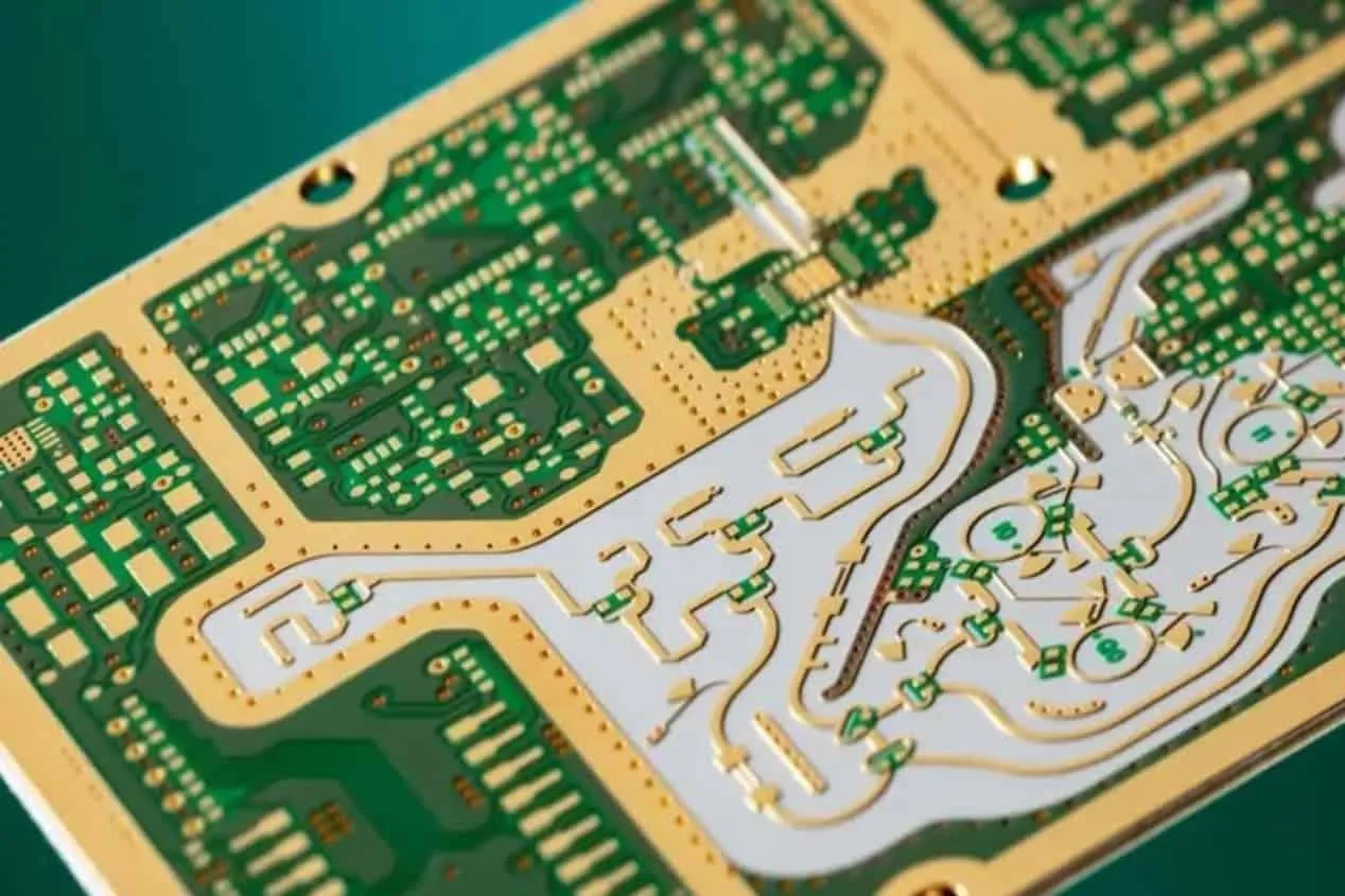
Rogers materials are specialized laminates designed for high-frequency and low-loss PCB materials applications. They are often made from hydrocarbon ceramics or PTFE (polytetrafluoroethylene) composites, offering superior electrical properties compared to standard materials like FR4.
Advantages of Rogers PCB
- Low Dissipation Factor: Rogers materials often have a Df as low as 0.001 to 0.003, minimizing signal loss even at frequencies up to 10 GHz or higher.
- Stable Dielectric Constant: With Dk values ranging from 2.2 to 10.2 (depending on the specific grade), Rogers offers consistent performance across a wide frequency range.
- Excellent Thermal Stability: Many Rogers laminates have a Tg exceeding 200°C, making them suitable for harsh environments.
- High-Frequency Performance: These materials are specifically engineered for RF and microwave applications, ideal for 5G base stations.
Limitations of Rogers PCB
- Higher Cost: Rogers materials are significantly more expensive than FR4, sometimes costing 5-10 times more per square foot.
- Processing Challenges: Some Rogers laminates require specialized fabrication techniques, increasing production complexity.
For telecommunication base stations that demand high-frequency performance and low signal loss, Rogers materials are often the preferred choice, especially for applications like 5G antennas and RF modules.
Comparative Analysis: FR4 vs. Rogers for Telecommunication Base Stations
To make an informed decision on PCB material selection, let’s break down the comparison between FR4 and Rogers across key performance metrics relevant to telecommunication base stations.
| Property | FR4 PCB | Rogers PCB |
|---|---|---|
| Dielectric Constant (Dk) | ~4.5 (varies with frequency) | 2.2 to 10.2 (stable across frequencies) |
| Dissipation Factor (Df) | ~0.02 | 0.001 to 0.003 |
| Frequency Range | Up to 1 GHz (limited beyond) | Up to 10 GHz and beyond |
| Thermal Stability (Tg) | 130-140°C | 200°C and higher |
| Cost | Low (affordable) | High (5-10x more than FR4) |
Signal Integrity and Loss
In high-frequency applications, signal integrity is paramount. FR4’s higher Df of 0.02 means it loses more signal energy as heat, which can degrade performance in 5G base stations operating at 3.5 GHz or higher. In contrast, Rogers materials, with a Df as low as 0.001, ensure minimal signal loss, making them ideal for maintaining data integrity over long distances.
Impedance Stability
Impedance matching is crucial for RF circuits in base stations. FR4’s Dk varies with frequency and temperature, leading to potential mismatches. Rogers materials offer a wider range of stable Dk values, ensuring consistent impedance even in dynamic conditions.
Thermal Management
Base stations often face temperature fluctuations, especially in outdoor installations. FR4 can deform or degrade at temperatures above 140°C, whereas Rogers materials remain stable at 200°C or more, ensuring reliability in high-power scenarios.
Cost vs. Performance Trade-Off
While Rogers outperforms FR4 in almost every technical aspect, the cost difference is significant. For base stations operating at lower frequencies or in less demanding environments, FR4 might suffice. However, for cutting-edge 5G networks where performance cannot be compromised, investing in Rogers is often worth the expense.
Practical Applications in Telecommunication Base Stations
Let’s look at how these materials fit into real-world scenarios for telecommunication infrastructure:
- 4G Base Stations: Many 4G systems operate below 2.6 GHz, where FR4 can handle the frequency demands without significant signal loss. Its low cost makes it a practical choice for widespread deployment.
- 5G Base Stations: 5G networks often use frequencies between 3.5 GHz and 6 GHz, or even higher in millimeter-wave bands. Here, Rogers materials are almost essential due to their low-loss properties and ability to support high-speed data transmission.
- RF and Antenna Modules: For components like RF transceivers and antennas, where signal clarity is critical, Rogers provides the necessary performance to minimize interference and maximize range.
How to Choose the Right Material for Your Project
Selecting between FR4 and Rogers for your telecommunication base station PCB comes down to a few key considerations:
- Frequency Requirements: If your system operates below 1-2 GHz, FR4 might be sufficient. For higher frequencies, especially in 5G, opt for Rogers.
- Budget Constraints: If cost is a primary concern, start with FR4 for non-critical components and reserve Rogers for high-performance areas.
- Environmental Conditions: For outdoor base stations exposed to extreme temperatures, Rogers offers better reliability.
- Signal Integrity Needs: If your application demands minimal signal loss and high data rates, prioritize low-loss PCB materials like Rogers.
By aligning your material choice with these factors, you can strike the right balance between performance and cost.
Conclusion: Making an Informed Decision for Telecommunication PCBs
Choosing the right material for telecommunication base station PCBs is a critical step in ensuring reliable, high-performance communication systems. While FR4 offers a cost-effective solution for lower-frequency applications, Rogers stands out as the superior choice for high-frequency PCB materials and low-loss PCB materials in demanding 5G environments.
Ultimately, your decision should be guided by the specific needs of your project, including frequency range, environmental conditions, and budget. By understanding the strengths and limitations of FR4 and Rogers, you can optimize your PCB design for both performance and efficiency. At ALLPCB, we’re committed to supporting your journey with expert guidance and high-quality manufacturing solutions tailored to your unique requirements.


