 ALLPCB


Designing a cost-effective pet tracker PCB is crucial for creating an affordable yet reliable device to keep pets safe. By focusing on pet tracking PCB cost optimization, low cost pet tracker PCB design, and BOM cost reduction for pet trackers, you can build a product that meets market demands without breaking the bank. In this comprehensive guide, we’ll walk you through practical strategies, component choices, and manufacturing tips to achieve an efficient and budget-friendly pet tracking solution.
Why Cost Optimization Matters in Pet Tracker PCB Design
Pet trackers are in high demand as pet owners seek ways to monitor their animals’ locations in real-time. However, with growing competition, keeping production costs low while maintaining quality is a top priority for manufacturers. A well-designed PCB (Printed Circuit Board) is the heart of any pet tracker, integrating components like GPS modules, communication systems, and power management. Optimizing the PCB design and component selection directly impacts the overall cost, making it accessible to a wider audience.
Cost optimization doesn’t mean cutting corners. It’s about smart choices—selecting affordable PCB materials, minimizing design complexity, and leveraging efficient PCB manufacturing processes. Let’s dive into the key areas where you can save costs without sacrificing performance.

Key Strategies for Pet Tracking PCB Cost Optimization
To achieve a budget-friendly pet tracker, focus on the following strategies during the design and production phases. These approaches ensure that you reduce expenses while maintaining functionality.
1. Simplify the PCB Layout for Lower Manufacturing Costs
A complex PCB layout with multiple layers or intricate routing increases manufacturing costs. For pet trackers, which often require compact designs, aim for a simple, two-layer board whenever possible. Reducing the number of layers cuts down on material and fabrication expenses. For example, a two-layer PCB can cost around 30-50% less than a four-layer board for small-scale production runs.
Additionally, optimize the board size to fit within standard panel dimensions during manufacturing. A smaller board not only uses less material but also allows more units to be produced per panel, reducing waste and cost. Keep trace widths and spacing at standard values (e.g., 6 mil trace width and spacing) to avoid the need for specialized manufacturing processes that drive up expenses.
2. Choose Affordable PCB Materials
The choice of material plays a big role in PCB cost. For pet trackers, which don’t typically require high-frequency performance, standard FR-4 material is a cost-effective and reliable option. FR-4 is widely available, durable, and suitable for most GPS and communication circuits, with costs averaging $0.10 to $0.20 per square inch for standard thicknesses (1.6mm).
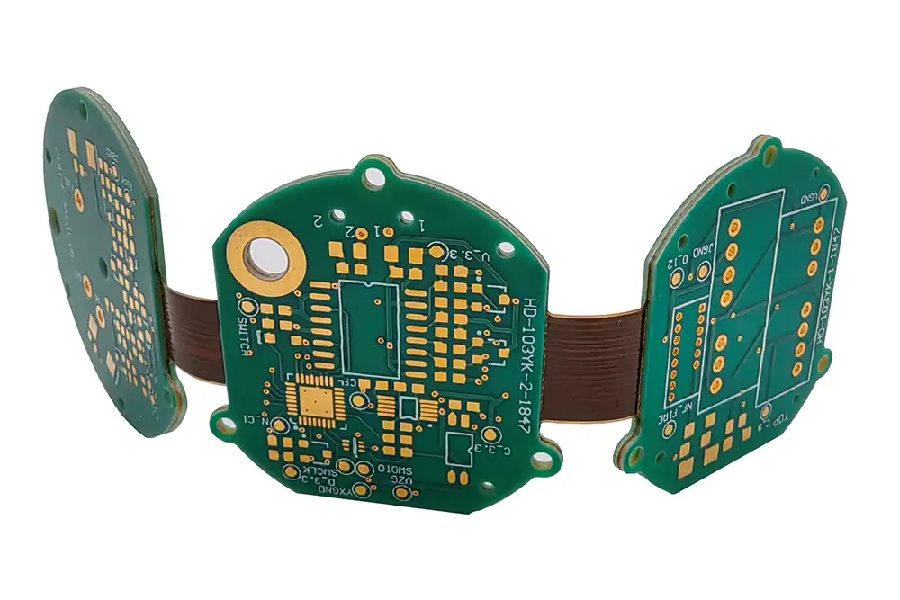
Avoid exotic materials like high-Tg FR-4 or flexible substrates unless absolutely necessary for specific design constraints. If flexibility is needed for a collar-mounted tracker, consider using polyester (PET) films for flexible circuits, which are more affordable than polyimide-based options and still provide decent performance for low-speed signals.
3. Optimize Component Selection for BOM Cost Reduction in Pet Trackers
The Bill of Materials (BOM) often accounts for a significant portion of the total cost of a pet tracker. Here are some tips to reduce BOM expenses without compromising functionality:
- Use Widely Available Components: Opt for generic or widely stocked components rather than specialized parts. For instance, choose a common GPS module with a proven track record over a niche, high-end option. A basic GPS module can cost as low as $5 per unit in bulk, compared to $15 or more for advanced models with unnecessary features.
- Integrate Multi-Function Chips: Select microcontrollers (MCUs) or System-on-Chip (SoC) solutions that combine multiple functions like processing, Bluetooth, and power management into a single package. This reduces the number of components on the board, saving space and cost. Some SoCs for IoT applications are priced under $2 per unit at volume.
- Minimize Passive Components: Reduce the count of resistors, capacitors, and inductors by optimizing the circuit design. Use standard values (e.g., 1kΩ resistors, 0.1μF capacitors) that are cheaper and easier to source.
By carefully auditing your BOM and prioritizing cost-effective parts, you can achieve significant savings. For instance, reducing the BOM cost by just $2 per unit on a production run of 10,000 trackers saves $20,000 overall.
Low-Cost Pet Tracker PCB Design Techniques
Designing a pet tracker PCB with cost in mind requires balancing functionality with simplicity. Below are actionable techniques to guide your design process.
1. Focus on Power Efficiency to Reduce Battery Costs
Pet trackers rely on batteries for portable operation, and battery life is a key selling point. Designing for power efficiency not only improves user experience but also reduces costs by allowing the use of smaller, cheaper batteries. Incorporate low-power components, such as MCUs with sleep modes that draw less than 1μA in standby. For example, a low-power GPS module might consume 20mA during active tracking, compared to 50mA for standard models.
Additionally, implement power-saving features like duty cycling, where the tracker only activates GPS at intervals (e.g., every 5 minutes) unless triggered by motion. This extends battery life, allowing you to use a smaller capacity battery, which can cut costs by 20-30% per unit.
2. Integrate Antennas on the PCB
External antennas for GPS or cellular communication add to the BOM cost and assembly complexity. Instead, design a PCB trace antenna for GPS or Bluetooth signals. A well-designed trace antenna can achieve a gain of -3 to -1 dBi, sufficient for most pet tracking applications within urban areas. This eliminates the need for a separate component, saving around $0.50 to $1.00 per unit.
Ensure proper placement of the antenna away from noisy components like power regulators to avoid interference. Use simulation tools to optimize the antenna layout for a 50-ohm impedance match, ensuring reliable signal reception without additional tuning components.
3. Design for Manufacturability (DFM)
A PCB designed with manufacturing in mind reduces errors, rework, and costs during production. Follow these DFM guidelines for a low cost pet tracker PCB design:
- Standardize Hole Sizes: Use common drill sizes (e.g., 0.8mm or 1.0mm) for vias and mounting holes to avoid custom tooling fees.
- Avoid Tight Tolerances: Unless critical, stick to standard tolerances for trace widths and clearances to prevent additional manufacturing steps.
- Panelize Efficiently: Design the PCB to fit multiple units on a single panel, reducing material waste and lowering per-unit costs by up to 10-15%.
Efficient PCB Manufacturing for Pet Trackers
Manufacturing efficiency is just as important as design when it comes to cost savings. Partnering with a reliable fabrication and assembly service can make a big difference in achieving efficient PCB manufacturing for pet trackers.
1. Leverage Bulk Ordering
Ordering components and PCBs in bulk significantly reduces per-unit costs. For example, producing 5,000 PCBs might cost $1.50 per board, while a run of 500 could cost $5 per board due to setup fees and economies of scale. Plan production runs to maximize volume discounts on both materials and assembly services.
2. Opt for Automated Assembly
Automated Surface Mount Technology (SMT) assembly is faster and cheaper than manual assembly for large runs. Ensure your design uses surface-mount components wherever possible, as through-hole parts often require manual soldering, increasing labor costs by 20-30%. Work with a manufacturing partner that offers competitive SMT assembly rates to keep expenses low.
3. Test Early and Often
Incorporate test points into your PCB design to facilitate in-circuit testing (ICT) during manufacturing. Catching defects early prevents costly rework or recalls. For instance, a simple test point for power and ground can help verify connections before full assembly, saving time and reducing scrap rates by up to 5%.
Balancing Cost and Performance in Pet Tracker PCBs
While cost reduction is the goal, it’s important not to compromise on the core functionality of a pet tracker. Ensure that the device provides accurate GPS tracking (within 5-10 meters), reliable communication (via cellular or Bluetooth), and a battery life of at least 24-48 hours. Cutting costs on critical components like the GPS module or battery can lead to poor performance, damaging the product’s reputation.
For example, while a $5 GPS module is tempting, verify that it supports necessary features like Assisted GPS (A-GPS) for faster location fixes, which can reduce power consumption by up to 30%. Similarly, invest in a decent quality battery with a capacity of at least 300mAh to avoid frequent recharges, even if it costs an extra $0.50 per unit.
Final Thoughts on Cost-Effective Pet Tracker PCB Design
Creating a cost-effective pet tracker PCB is achievable through careful planning, smart component choices, and efficient manufacturing practices. By focusing on pet tracking PCB cost optimization, employing low cost pet tracker PCB design techniques, and prioritizing BOM cost reduction for pet trackers, you can produce a high-quality device at a competitive price point. Using affordable PCB materials like FR-4 and leveraging efficient PCB manufacturing processes further ensures that costs remain low without sacrificing reliability.
Whether you’re a startup looking to enter the pet tech market or an established manufacturer aiming to reduce expenses, these strategies provide a clear roadmap to success. Start by simplifying your design, selecting budget-friendly components, and partnering with a trusted fabrication service to bring your vision to life.


