ALLPCB


Security cameras are essential for safety and surveillance, but when their printed circuit boards (PCBs) fail, it can lead to costly downtime or compromised security. If you're a technician searching for solutions to issues like "security camera PCB repair" or "CCTV PCB troubleshooting," you're in the right place. This guide provides a detailed, step-by-step approach to diagnosing PCB failures in security cameras, fixing broken security camera PCBs, and mastering security camera PCB rework. Whether you're dealing with power issues, signal loss, or component damage, we'll walk you through practical solutions to get your systems back online.
In the following sections, we'll dive deep into common problems, diagnostic techniques, repair methods, and preventive tips to help you tackle PCB issues with confidence. Let’s get started with ALLPCB!
Why Do Security Camera PCBs Fail?
Understanding the root causes of PCB failures in security cameras is the first step to effective troubleshooting. These boards are the heart of any CCTV system, controlling power distribution, video processing, and data transmission. Failures can disrupt the entire system, and they often stem from a few common issues:
- Power Surges and Overvoltage: Security cameras are often exposed to fluctuating power supplies, especially in outdoor setups. A surge above the typical 12V DC input (common for most cameras) can fry components like capacitors or voltage regulators.
- Environmental Damage: Moisture, dust, and extreme temperatures can corrode traces or damage components. For instance, humidity levels above 85% can lead to oxidation on solder joints.
- Physical Stress: Vibrations or improper handling during installation can crack solder joints or dislodge surface-mount components.
- Component Aging: Over time, components like electrolytic capacitors degrade, often failing after 2-5 years of continuous operation, leading to power instability.
- Manufacturing Defects: Poor soldering, weak traces, or low-quality components can cause failures right out of the box or after minimal use.
By recognizing these causes, technicians can narrow down potential issues during CCTV PCB troubleshooting and take steps to prevent future problems.
Essential Tools for Diagnosing PCB Failures in Security Cameras
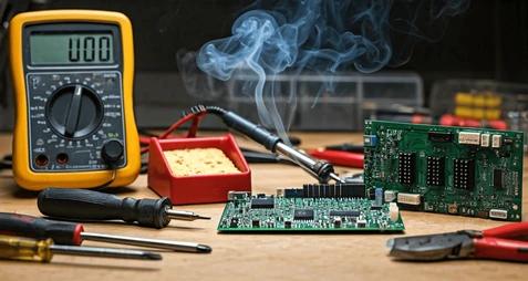
Before diving into repairs, having the right tools is critical for accurate diagnostics and safe rework. Here’s a list of must-have equipment for security camera PCB repair:
- Multimeter: For measuring voltage, resistance, and continuity. Essential for checking power supply lines (e.g., ensuring a stable 12V or 24V input) and identifying short circuits.
- Oscilloscope: Useful for analyzing video signal output or clock signals, often operating at frequencies like 27 MHz for standard CCTV systems.
- Soldering Iron and Hot Air Rework Station: Needed for replacing components or reflowing solder joints. Use a fine-tip iron (15-30W) for precision on small SMD parts.
- Magnifying Glass or Microscope: To inspect tiny solder joints or hairline cracks on traces, especially on densely packed boards.
- Desoldering Tools: Wick or a desoldering pump to remove old solder without damaging pads.
- ESD Protection: Anti-static wrist straps and mats to prevent static discharge, which can damage sensitive ICs.
With these tools in hand, you’ll be well-equipped to start diagnosing and fixing broken security camera PCBs.
Step-by-Step Guide to Diagnosing PCB Failures in Security Cameras
Diagnosing issues in security camera PCBs requires a systematic approach to pinpoint the problem efficiently. Follow these steps to identify failures accurately:
1. Visual Inspection
Start by examining the PCB under good lighting with a magnifying tool. Look for:
- Burnt or discolored components, which indicate overheating or short circuits.
- Cracked solder joints or broken traces, often caused by physical stress.
- Swollen or leaking capacitors, a common sign of failure in power circuits.
- Corrosion or residue from moisture exposure, especially near connectors.
2. Power Supply Testing
Use a multimeter to verify the input voltage. Most security cameras operate on 12V or 24V DC. If the voltage is outside the expected range (e.g., below 11V or above 14V for a 12V system), the issue might be with the power adapter or internal regulator. Check for:
- Continuity in power traces to ensure there are no breaks.
- Short circuits between power and ground planes, often caused by solder bridges.
3. Signal Testing
If the camera powers on but shows no video output, the issue could be in the signal processing section. Use an oscilloscope to measure video output signals (typically analog CVBS at 1V peak-to-peak or digital signals for IP cameras). Look for:
- Absent or distorted signals, which may point to a failed image sensor or processing IC.
- Clock signal issues, often around 27 MHz, which can disrupt video encoding.
4. Component Testing
Test individual components like resistors, capacitors, and diodes with a multimeter. For example, a capacitor in the power filter circuit should show a capacitance value close to its rated spec (e.g., 100μF ±10%). Replace any component that deviates significantly from its expected value.

Common Issues and Fixes for Security Camera PCBs
Now that you’ve diagnosed the problem, let’s explore specific issues and how to fix broken security camera PCBs. Below are the most common failures and their solutions:
1. No Power or Intermittent Power
Cause: Failed voltage regulators, blown fuses, or damaged capacitors in the power circuit.
Fix:
- Check the input fuse or diode for continuity. Replace if open.
- Test the voltage regulator (e.g., a 7805 for 5V output) to ensure it’s providing the correct voltage. If not, replace it with a compatible part.
- Inspect electrolytic capacitors near the power input. A capacitance drop below 80% of the rated value (e.g., 80μF for a 100μF cap) indicates failure—replace with a part of the same rating.
2. No Video Output
Cause: Faulty image sensor, damaged video processing IC, or broken signal traces.
Fix:
- Verify power to the image sensor (typically 3.3V or 5V). If absent, trace the power line for breaks or shorts.
- Use an oscilloscope to check for video output signals. If none are present, the sensor or processing chip may need replacement—a delicate task requiring a hot air rework station.
- Inspect traces between the sensor and output connector for continuity. Repair broken traces using conductive epoxy or fine wire if needed.
3. Distorted or Noisy Video
Cause: Interference, failing capacitors in the signal path, or grounding issues.
Fix:
- Check grounding points for proper connection. Poor grounding can introduce noise into the video signal.
- Replace capacitors in the signal filter circuit (often small ceramic caps rated at 0.1μF) if they show irregular readings.
- Shield signal cables if external interference is suspected, especially in setups near high-power equipment.
4. Overheating Components
Cause: Overloaded circuits, poor heat dissipation, or failing components drawing excessive current.
Fix:
- Identify hot components using a thermal camera or by touch (carefully). Common culprits are voltage regulators or power transistors.
- Ensure proper airflow around the camera housing to prevent heat buildup.
- Replace overheating components and consider adding small heat sinks if the design allows.
Security Camera PCB Rework Techniques
Reworking a PCB involves removing and replacing components or repairing traces without causing further damage. Security camera PCB rework requires precision, especially with small surface-mount devices (SMDs). Here are key techniques:
1. Component Removal
Use a hot air rework station set to around 300°C to desolder SMD components. Apply flux to the solder joints to lower the melting point and prevent pad damage. Gently lift the component with tweezers once the solder melts.
2. Component Replacement
Clean the pads with desoldering wick and isopropyl alcohol (90% or higher). Apply fresh solder paste or flux, then position the new component. Use the hot air station or a soldering iron to reflow the solder, ensuring even distribution across all pins.
3. Trace Repair
For broken traces, scrape off the solder mask to expose the copper. Solder a thin jumper wire (e.g., 30 AWG) between the disconnected points, securing it with epoxy for durability. Test for continuity after repair.
Preventive Maintenance Tips for Security Camera PCBs
Preventing issues is just as important as fixing them. Here are practical tips to extend the lifespan of security camera PCBs:
- Use Surge Protectors: Install surge protection devices to shield against voltage spikes, especially for outdoor cameras.
- Seal Against Moisture: Apply conformal coating to PCBs in humid environments to protect against corrosion.
- Regular Inspections: Schedule periodic checks (every 6-12 months) to catch early signs of wear, like bulging capacitors or loose connections.
- Proper Installation: Secure cameras to minimize vibration and ensure adequate ventilation to prevent overheating.
Conclusion
Troubleshooting and repairing security camera PCBs doesn’t have to be daunting. By following a structured approach to CCTV PCB troubleshooting, using the right tools, and applying proven repair techniques, technicians can tackle common issues like power failures, video loss, and overheating components. Whether you’re diagnosing PCB failures in security cameras or performing intricate security camera PCB rework, the steps outlined in this guide provide a solid foundation for success. With proper care and preventive measures, you can ensure your surveillance systems remain reliable for years to come.
Armed with this knowledge, you’re ready to handle the challenges of security camera PCB repair with confidence. Keep learning, stay equipped, and maintain the integrity of your surveillance setups with these practical strategies.