ALLPCB


A power-on reset (POR) ensures that when a circuit or system is powered on, specific circuitry or electronic components restore all parts of the system to a known initial state. This allows the system to start up in a reliable and predictable manner.
When a circuit or system is powered on after being off for a period, it may face unknown states or abnormal conditions. For example, internal registers may not be properly cleared, logic levels may be uninitialized, or external devices may not be initialized. These unknown states can cause the system to operate incorrectly or produce errors.
To solve this problem, a power-on reset circuit generates a reset signal when the power is applied. This signal is sent to various parts of the system to trigger the initialization process. The reset signal can set logic levels to a known state, clear register contents, and initialize external devices, ensuring the entire system starts in a controlled state.
By using a power-on reset, unknown system states are avoided, guaranteeing that the system begins operation from a stable and controlled condition. Power-on reset is commonly used in various electronic devices and systems, including microprocessors, microcontrollers, embedded systems, and integrated circuits. It is a critical part of ensuring system reliability and proper functionality.
Key Components in Power-On Reset Circuits
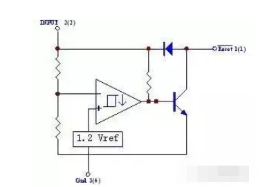
A key component used in these circuits is the MC34064.
Internal block diagram:
Input-output characteristic curve:
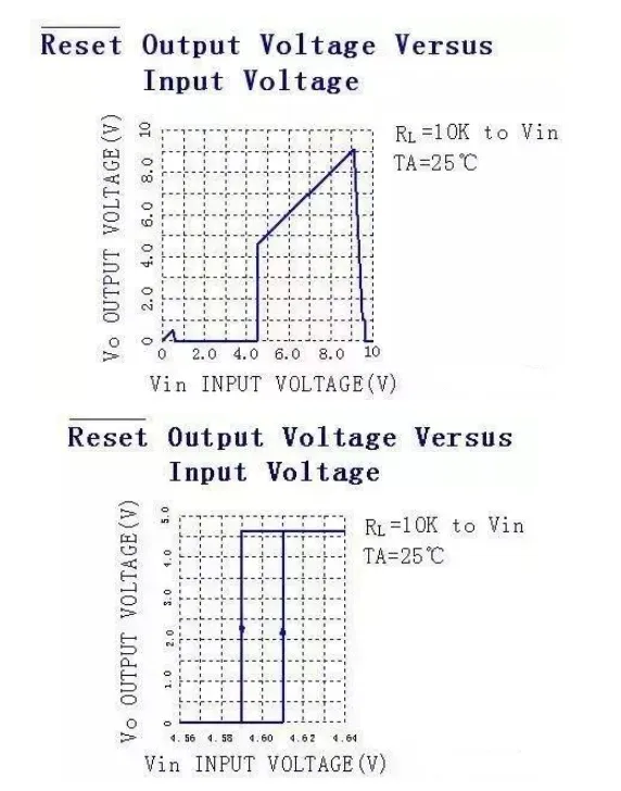
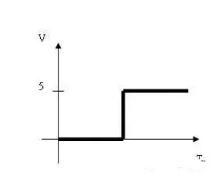
The output of pin 1 of the MC34064 (after stabilization) is shown in the figure below:
Types of Power-On Reset Circuits
Power-on reset circuits can be classified based on their implementation method and functional characteristics. The following are some common types:
- Reset circuits based on power supply monitoring ICs: These circuits use specialized power supply monitoring ICs (supervisors) to generate a reset signal by monitoring the supply voltage. These ICs typically have adjustable thresholds and delay functions to suit different application needs.
- Reset circuits based on logic gates: These circuits use logic gates to generate a reset signal by taking the power supply voltage and other control signals as inputs. They can range from simple combinatorial logic circuits to more complex gate arrays or programmable logic devices like FPGAs.
- Internal microcontroller reset circuits: Many microcontrollers (MCUs) have built-in reset circuitry that automatically generates a reset signal on power-up. These internal circuits can often be configured and adjusted through the chip's internal configuration bits.
- External manual reset circuits: These circuits consist of buttons, switches, or other manual input components, allowing a user to trigger a reset manually. Manual reset circuits are often used for troubleshooting, system debugging, and during development.
- Reset delay circuits: Some power-on reset circuits include a delay element to extend the duration of the reset signal. The delay time can be configured based on system requirements and is often implemented using resistor-capacitor (RC) networks.
These are common classifications, and specific reset circuit designs may be customized according to application requirements and system characteristics.