Overview
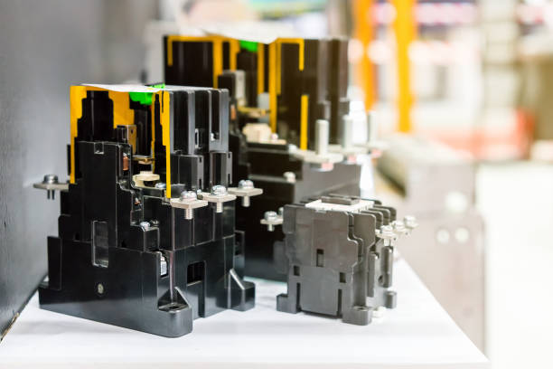
You can typically distinguish 380V AC contactor models by the following methods:
- Observe exterior markings: Contactors usually have model information on the housing, which may include manufacturer name, model number, rated voltage, rated current, and other details. Inspecting and recording these markings helps distinguish different models.
- Consult product documentation or manuals: If you have the product documentation or manual, check it for model information. Manuals typically describe the model, specifications, and performance parameters in detail.
- Online search: Use a search engine to query the contactor brand and model. You can often find technical data, product manuals, or supplier information that provide detailed specifications.
- Contact the supplier or manufacturer: If the above methods do not yield the needed model information, contact the supplier or manufacturer to confirm the specific model and specifications.
A model designation is not just a combination of letters or numbers; it also encodes important parameters such as rated voltage, rated current, and rated capacity.
Physical Wiring Diagram for a 380V AC Contactor
The diagram shows a control circuit composed of a 3-pole circuit breaker for the power supply, a 1-pole circuit breaker for the control circuit, a green start button (a pair of normally open contacts 3-4), a stop button (a pair of normally closed contacts 1-2), two 380V indicator lamps, and a 380V AC contactor with a working pull-in coil. A thermal overload relay can be connected in series with the contactor to protect a three-phase induction motor. The normally closed contact of the thermal relay should be placed in series with the 380V pull-in coil circuit. When the motor is overloaded, the bimetal element in the thermal relay deforms and opens the auxiliary contact, which stops the contactor and protects the motor. The simple start/lock/stop control circuit is formed by these components together with a three-phase induction motor.
Operation: Close the three-phase breaker and close the 1-pole breaker for the control circuit to supply 3×380V working power (also denoted L1, L2, L3; any two phase lines have a line voltage of 380V). When the start button is pressed, its normally open contact closes. Current flows from the lower terminal of the 1-pole breaker through the stop button's normally closed contact 1-2, then through the start button 3-4, and onward through the contactor's auxiliary normally open contact. The current then enters one terminal of the 380V coil; the other terminal is connected directly to one of the power lines. This completes the coil circuit, so the coil generates magnetic force and pulls in the contactor. At this point, the auxiliary normally open contact changes to closed, and the auxiliary contact holds the latch function so the start button no longer needs to be pressed.
How to Assess 380V AC Contactor Condition
Methods to determine whether a 380V AC contactor is functioning properly include:
- Observe operating state: A properly functioning contactor should reliably pick up and drop out without abnormal noises or smells. Inspect for visible burning, melting, deformation, or severe oxidation.
- Check contact condition: Inspect the main and auxiliary contacts for wear, oxidation, or burning. Contacts should be clean, flat, and smooth.
- Measure contact resistance: Use a multimeter or contact resistance tester to measure the contact resistance. A normally operating contactor will typically have contact resistance in the range of tens to a few hundred milliohms (mΩ).
- Check the electromagnetic coil: Use a multimeter or voltmeter to measure the coil resistance or coil voltage. A working coil should show appropriate resistance and respond to the correct coil voltage.
- Verify rated voltage and current: Confirm that the contactor's rated voltage and current match the actual operating conditions. Using a contactor beyond its rated voltage or current can cause damage or malfunction.
Before performing any inspections or measurements, ensure the relevant circuits are de-energized and follow standard safety procedures.
 ALLPCB


