 ALLPCB


If you're looking for practical advice on drilling and drill file preparation for printed circuit boards (PCBs), you've come to the right place. This guide will cover essential tips on selecting the right drill bits, working with laminate materials, and creating accurate drill files to ensure precision in your PCB manufacturing process. Whether you're a hobbyist or a professional engineer, these insights will help streamline your workflow and improve the quality of your boards.
In this detailed blog post, we'll dive into the intricacies of PCB drilling, explore the best practices for handling laminate materials, and provide actionable steps for generating drill files that meet manufacturing standards. Let's get started with everything you need to know to achieve flawless results in your PCB projects.
Why Drilling Matters in PCB Manufacturing
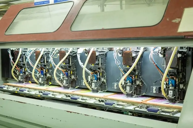
Drilling is one of the most critical steps in PCB manufacturing. It’s the process where holes are created in the board to accommodate through-hole components, vias, and mounting hardware. A single mistake in drilling—whether it's an incorrect hole size or misalignment—can render a board unusable, leading to costly delays and rework. Precision in this stage directly impacts the functionality and reliability of the final product.
Beyond just creating holes, drilling also involves working with various laminate materials, each with unique properties that affect how drill bits perform. Understanding these factors, along with proper drill file preparation, ensures that your boards are manufactured without errors. Let’s break this down step by step.
Understanding Drill Bits for PCB Drilling
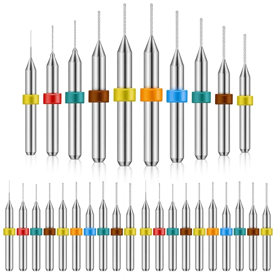
Choosing the right drill bits is essential for achieving clean, accurate holes in PCBs. Drill bits for PCB manufacturing are typically made from high-speed steel (HSS) or tungsten carbide due to their durability and ability to handle the abrasive nature of laminate materials. Here are some key considerations when selecting drill bits:
- Material: Tungsten carbide bits are preferred for their hardness and resistance to wear, especially when drilling through tough laminates like FR-4. They can handle high-speed operations without dulling quickly, making them ideal for large production runs.
- Size: PCB drill bits range from as small as 0.2 mm to over 6 mm, depending on the hole requirements. Smaller bits are used for vias, while larger ones are for mounting holes. Always match the bit size to the design specifications to avoid issues like loose components or broken bits.
- Coating: Some drill bits come with coatings like titanium nitride to reduce friction and heat buildup. This is particularly useful when drilling through thicker or multi-layer boards where heat dissipation is a concern.
- Flute Design: The flute design affects how debris is removed during drilling. Spiral flutes are common for PCB drilling as they efficiently clear out material, preventing clogging and overheating.
When drilling, it’s also important to consider the spindle speed and feed rate. For instance, a spindle speed of 60,000 to 80,000 RPM is often used for small-diameter bits (under 1 mm) to achieve clean cuts without breaking the bit. However, slower speeds of around 20,000 RPM may be better for larger bits to avoid excessive heat.
Navigating Laminate Materials in PCB Drilling
The type of laminate material used in your PCB plays a significant role in the drilling process. Laminates are the base materials that form the structure of the board, and their composition affects how drill bits interact with the surface. Let’s look at some common laminate types and tips for drilling them effectively:
FR-4 Laminate
FR-4 is the most widely used laminate material in PCB manufacturing due to its balance of cost, durability, and electrical insulation properties. Made from woven fiberglass and epoxy resin, it’s relatively easy to drill but can be abrasive on drill bits. To prevent excessive wear, use carbide bits and maintain a moderate feed rate to avoid burning the material. A feed rate of 50 to 100 inches per minute (IPM) is often recommended for FR-4, depending on the bit size and board thickness.
High-Tg Laminates
High-Tg (glass transition temperature) laminates are designed for applications requiring better thermal stability, often used in high-performance electronics. These materials are harder than standard FR-4, so they demand sharper, more durable drill bits and slower drilling speeds to prevent cracking or delamination. A spindle speed reduction to around 40,000 RPM can help manage heat buildup.
Rogers and Other RF Laminates
For high-frequency applications, laminates like those made from PTFE (polytetrafluoroethylene) or ceramic-filled materials are common. These are softer than FR-4 but can be slippery, making it harder to achieve clean holes. Use bits with a sharper cutting edge and lower feed rates (around 30 IPM) to maintain control and avoid tearing the material.
Regardless of the laminate, always ensure proper backing material during drilling to prevent exit burrs. A phenolic or aluminum backing plate can support the board and reduce damage to the bottom side of the holes.
Drill File Preparation: A Step-by-Step Guide
A drill file is a critical component of PCB design that tells the manufacturer where and how to drill holes on the board. Also known as an NC (numerical control) drill file, it contains precise coordinates and hole sizes for the drilling machine to follow. Preparing an accurate drill file minimizes errors during manufacturing. Here’s how to create one effectively:
- Export from Design Software: Most PCB design tools allow you to generate drill files directly from your layout. Ensure that you export the file in a format compatible with the manufacturer, such as Excellon or Gerber. Check the software settings to include all necessary layers, including plated and non-plated holes.
- Define Hole Sizes and Types: Clearly specify the diameter of each hole and whether it’s plated (for vias and through-hole components) or non-plated (for mounting holes). For example, a via might require a 0.3 mm hole, while a mounting hole could be 3.2 mm.
- Verify Coordinates: Drill files use X and Y coordinates to define hole locations. Double-check that these coordinates align with your PCB layout to avoid misplacement. Even a 0.1 mm deviation can cause alignment issues with components.
- Include a Drill Map or Report: Some manufacturers appreciate a drill map or report alongside the file. This is a visual or textual representation of the hole locations and sizes, making it easier to verify the design before drilling begins.
- Test with a Viewer: Before sending the file to the manufacturer, use a drill file viewer or CAM software to simulate the drilling pattern. This helps catch any errors, such as missing holes or incorrect sizes, before production starts.
Accurate drill files are especially important for multi-layer boards, where vias connect different layers. A misaligned via can disrupt signal integrity, leading to performance issues. For high-speed designs, ensure that via holes maintain a specific aspect ratio (typically less than 10:1 for diameter to depth) to avoid manufacturing challenges.
Common Challenges in PCB Drilling and How to Avoid Them
Even with the best preparation, drilling issues can arise. Here are some common problems and tips to prevent them:
- Burr Formation: Burrs are rough edges around drilled holes that can interfere with component placement. Use a sharp drill bit and a proper backing material to minimize burrs. If they do form, a light deburring process with a fine abrasive can clean up the edges.
- Drill Bit Breakage: Small-diameter bits are prone to breaking, especially at high speeds or with improper feed rates. Reduce spindle speed for bits under 0.5 mm and ensure the board is securely clamped to avoid vibration.
- Heat Damage: Excessive heat during drilling can burn the laminate or smear resin, affecting hole quality. Use appropriate speeds (e.g., 60,000 RPM for small bits) and ensure proper chip evacuation with well-designed flutes.
- Misalignment: If the drill file coordinates don’t match the board layout, holes may be misaligned. Always verify the drill file against the Gerber files and use alignment pins or fiducials during manufacturing setup.
By anticipating these challenges and taking preventive measures, you can save time and reduce the risk of defective boards.
Best Practices for Long-Lasting Drill Bits and Laminate Integrity
Maintaining your tools and materials is just as important as using the right techniques. Here are some best practices to extend the life of your drill bits and preserve laminate quality:
- Regular Bit Inspection: Check drill bits for wear or chipping after every few boards. A dull bit can cause rough holes and damage the laminate. Replace bits as soon as they show signs of wear.
- Clean Drilling Environment: Dust and debris can contaminate holes or cause uneven drilling. Use a vacuum system or compressed air to keep the workspace clean during drilling.
- Store Laminates Properly: Laminate materials are sensitive to moisture and temperature changes, which can cause warping or delamination. Store them in a dry, controlled environment to maintain their integrity before drilling.
- Use Coolant Sparingly: For high-speed drilling, a light mist of coolant can reduce heat. However, avoid overuse, as excessive coolant can seep into the laminate and affect its electrical properties.
Conclusion: Mastering PCB Drilling and Drill Files
Drilling is a cornerstone of PCB manufacturing that demands attention to detail, from selecting the right drill bits to preparing accurate drill files. By understanding the properties of laminate materials like FR-4 and high-Tg, you can adjust your drilling techniques to achieve clean, precise holes every time. Additionally, a well-prepared drill file ensures that the manufacturer can replicate your design without errors, saving time and resources.
Whether you're working on a simple single-layer board or a complex multi-layer design, these tech tips can help elevate the quality of your PCBs. Focus on using the correct tools, maintaining your equipment, and verifying your files to ensure success in every project. With these strategies in hand, you’re well-equipped to tackle the challenges of PCB drilling and deliver reliable, high-performance boards.


