 ALLPCB


Background
In EMC design, common strategies are "blocking" and "shunting". Inductors and ferrite beads are typically used for blocking, while capacitors are used for shunting. Shunting is often preferred because it guides return currents into low-impedance paths and reduces interference to other signals. Blocking can produce high voltages, which may create voltage-driven common-mode disturbances. Practical experience shows that appropriate selection and use of capacitors can resolve many EMC issues with good effect, low cost, and easy implementation. However, improper selection or use can fail to achieve the desired results or even worsen EMC performance. A common cause of incorrect capacitor choice is neglecting working voltage, operating frequency, or temperature. The following uses an ESD test from EMC work to illustrate capacitor selection and application.
Test Observation
During an ESD ±4kV pin discharge test on an automotive product, some pins showed RCL values that deviated by more than 10% between pre- and post-test measurements, which exceeds the test standard.
Initial Analysis
Data analysis revealed that pins which passed the ESD test had a 10nF capacitor added at the pin interface. Pins that failed had neither an ESD diode nor a 10nF capacitor; transistor circuits were directly exposed at the interface. The transistor datasheet indicated the device meets ±4kV HBM requirements, but the measured results show the port cannot pass the ESD discharge test without an ESD diode or a capacitive absorber at the interface.
Why a 10nF Capacitor Works
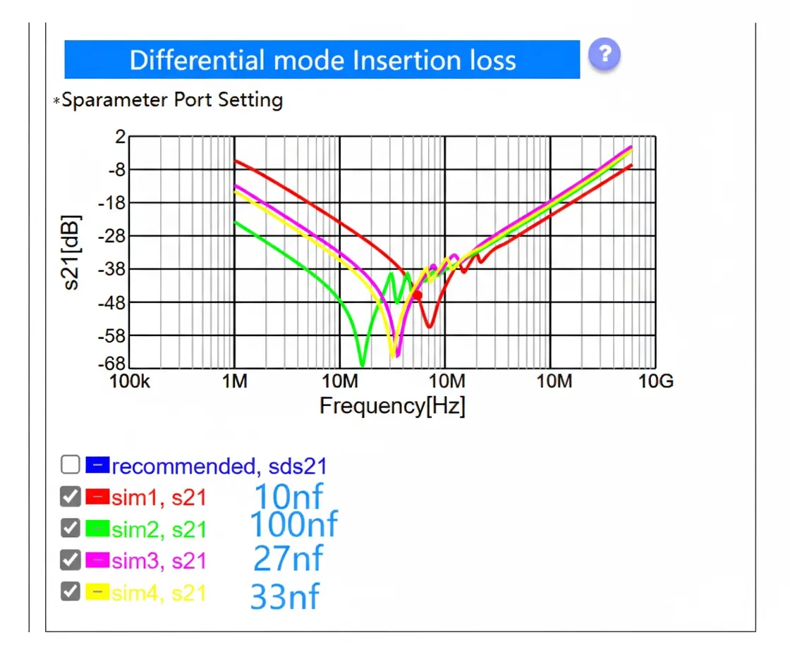
Consulting references shows ESD discharge energy is concentrated within the first 30 ns, and the spectral peak is near 50 MHz.
Insertion-loss simulations from Murata indicate 10nF, 27nF, and 33nF capacitors all show low impedance near 55 MHz. However, 27nF and 33nF are already above their self-resonant frequencies at that frequency and exhibit inductive behavior. That inductance can interact with other parasitic capacitances and form LC resonances, which may cause EMI. Therefore, a 10nF capacitor was selected.
Retest Results
After adding the 10nF capacitor, the ±4kV ESD test was repeated. The retest results show all pin RCL values remained within 10% before and after the test, meeting the acceptance criterion.
Conclusion
- When avoiding the use of an ESD diode for cost reasons, a 10nF capacitor at the pin interface can help pass a ±4kV pin discharge test.
- Because of manufacturing and component characteristics, a capacitor should be used at frequencies below its self-resonant frequency. Otherwise, it may become inductive and form parallel LC resonance with other capacitances, causing EMI issues.


