 ALLPCB


If you're facing challenges with air quality monitoring printed circuit boards (PCBs), you're not alone. Common issues like signal noise, sensor reading drift, power supply problems, connectivity hiccups, I2C communication errors, and sensor calibration troubles can disrupt the performance of air monitors. In this detailed guide, we'll walk you through practical solutions to troubleshoot and resolve these problems, ensuring your air quality monitoring systems operate smoothly and deliver accurate data.
Whether you're an engineer designing these systems or a technician maintaining them, this blog post will provide actionable insights into diagnosing and fixing issues with air quality monitoring PCBs. Let’s dive into the specifics of each problem, explore root causes, and outline step-by-step solutions.
Understanding Air Quality Monitoring PCBs
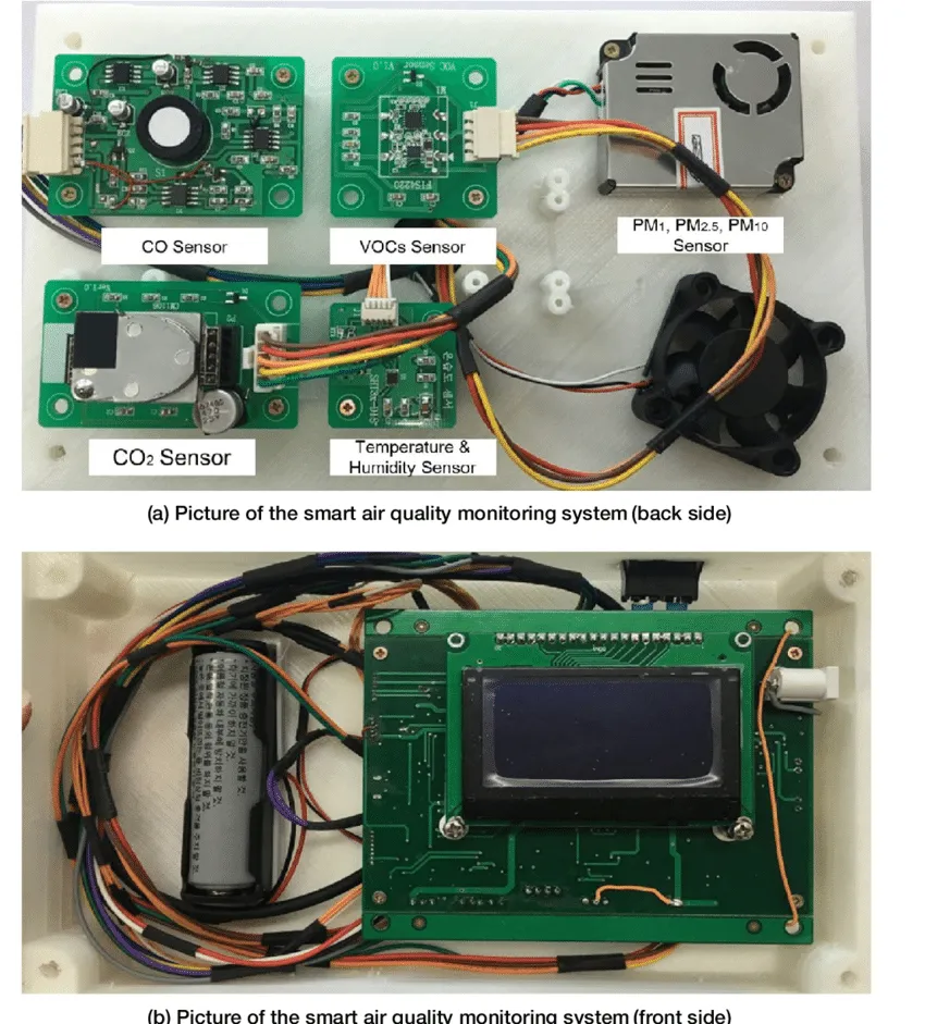
Air quality monitoring PCBs are the backbone of devices that measure pollutants, humidity, temperature, and other environmental factors. These boards integrate sensors, microcontrollers, and communication interfaces to collect and process data. However, due to the sensitive nature of the components and the environments they operate in, issues can arise that affect accuracy and reliability.
Below, we’ll cover the most common problems encountered in these systems, focusing on long-tail keywords like air quality PCB signal noise, sensor reading drift, power supply problems in air monitors, troubleshooting PCB connectivity, debugging I2C communication, and fixing sensor calibration issues. Each section includes practical tips and technical details to help you resolve these challenges.
1. Addressing Air Quality PCB Signal Noise
Signal noise is a frequent issue in air quality monitoring PCBs, often leading to inaccurate sensor readings. Noise can stem from electromagnetic interference (EMI), poor grounding, or improper PCB layout design. For instance, if a sensor signal line runs too close to a high-frequency switching regulator, it can pick up unwanted noise, distorting the output.
To troubleshoot air quality PCB signal noise, start by examining the PCB layout. Ensure that analog and digital ground planes are separated to minimize interference. Use shielding techniques, such as placing a ground plane beneath sensitive signal traces, to reduce EMI. Additionally, consider adding low-pass filters to sensor output lines to smooth out high-frequency noise. For example, a simple RC filter with a resistor of 1 kΩ and a capacitor of 0.1 μF can effectively cut off noise above 1.6 kHz.
Another approach is to check cable routing. If external cables connect sensors to the PCB, ensure they are shielded and kept away from power lines. Finally, verify that the PCB is housed in a metal enclosure if it operates in an environment with high EMI, such as near industrial equipment.
2. Fixing Sensor Reading Drift in Air Quality Monitors
Sensor reading drift occurs when sensor outputs gradually deviate from accurate measurements over time. This can be caused by environmental factors like temperature changes, aging of sensor components, or contamination on the sensor surface. For air quality monitors, this is critical as it directly impacts data reliability.
To address sensor reading drift, first, ensure that sensors are operating within their specified temperature and humidity ranges. For example, many particulate matter (PM) sensors are rated for 0°C to 50°C. Exceeding these limits can cause drift. If environmental control isn’t possible, consider using temperature compensation algorithms in your firmware to adjust readings based on ambient conditions.
Regular maintenance is also key. Dust or debris on sensors can skew readings, so clean them periodically using compressed air or a soft brush, following the manufacturer’s guidelines. If drift persists, recalibrate the sensor using a known reference source, which we’ll discuss in more detail later under calibration issues.

3. Solving Power Supply Problems in Air Monitors
Power supply problems in air monitors can lead to erratic sensor behavior, system resets, or complete failure. Common causes include voltage fluctuations, insufficient current capacity, or noise from the power source affecting sensitive components.
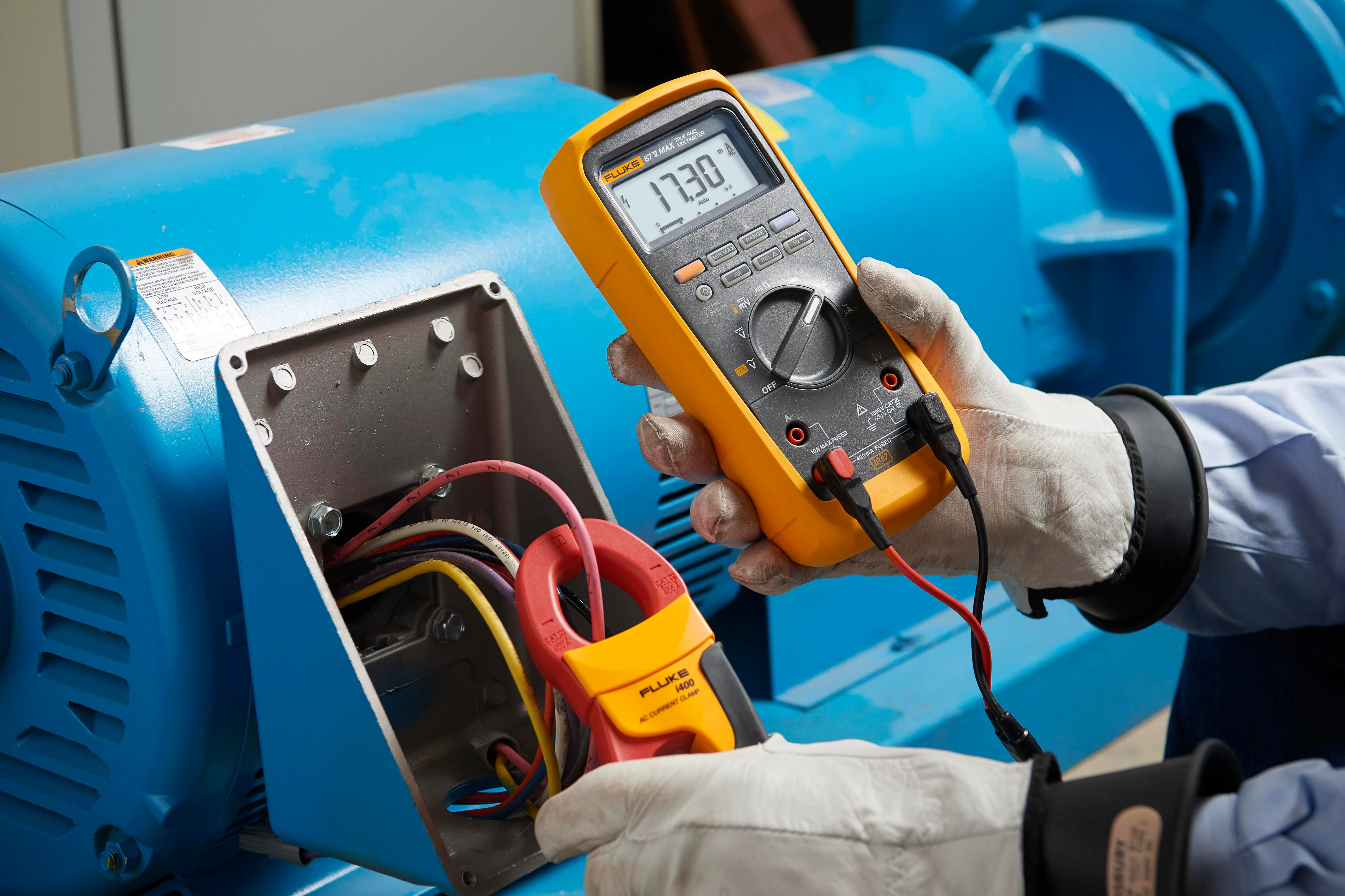
Start troubleshooting by measuring the input voltage to the PCB using a multimeter. Ensure it matches the specified range for your system, typically 3.3V or 5V for most air quality monitoring boards. If the voltage is unstable, check the power adapter or battery for issues. For instance, a switching power supply might introduce ripple noise, which can be mitigated by adding a decoupling capacitor (e.g., 10 μF) near the power input pin of the microcontroller.
Also, verify that the power supply can handle the current draw of all components. A typical air quality sensor might require 50-100 mA, while a microcontroller could draw another 20-50 mA. If the supply is underpowered, upgrade to a higher-capacity source. Finally, inspect for damaged traces or solder joints on the PCB that might interrupt power delivery.
4. Troubleshooting PCB Connectivity Issues
Troubleshooting PCB connectivity is essential when components on the board fail to communicate or when external connections are unreliable. Loose solder joints, damaged traces, or improper connector seating are common culprits in air quality monitoring systems.
Begin by visually inspecting the PCB for any visible damage, such as cracked traces or cold solder joints. Use a magnifying glass if needed to spot tiny defects. If you find a suspect area, reflow the solder joint with a soldering iron or repair the trace using a conductive pen for minor breaks.
For external connections, ensure that cables and connectors are securely plugged in and free of corrosion. If the system uses a modular design with multiple boards, check for alignment issues in connectors. A continuity test with a multimeter can help confirm if signals are passing through as expected. For instance, a reading of infinite resistance between two points that should be connected indicates a break.
5. Debugging I2C Communication Errors
Debugging I2C communication is often necessary in air quality monitoring PCBs since many sensors use the I2C protocol to communicate with microcontrollers. Issues like missing acknowledgments, data corruption, or bus lockups can prevent proper data transfer.
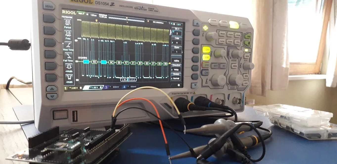
First, ensure that pull-up resistors are present on the SDA and SCL lines, typically in the range of 2.2 kΩ to 10 kΩ, depending on the bus speed and capacitance. Without these, the I2C lines may not return to a high state, causing communication failures. Use an oscilloscope to inspect the signal integrity on the I2C lines. Look for clean square waves; if the edges are rounded or noisy, it could indicate excessive capacitance or interference.
Next, check the device addresses in your code. Each I2C device on the bus must have a unique address, and a mismatch can halt communication. If multiple devices share the bus, scan for conflicts using a simple I2C scanner sketch on your microcontroller. Finally, ensure the bus speed is within the sensor’s supported range, often 100 kHz or 400 kHz, as exceeding this can cause errors.
6. Fixing Sensor Calibration Issues
Fixing sensor calibration issues is critical for maintaining the accuracy of air quality monitors. Over time, sensors can lose their calibration due to environmental exposure or component aging, leading to incorrect readings.
To recalibrate, you’ll need a reference standard, such as a certified gas mixture for gas sensors or a controlled environment for temperature and humidity sensors. Follow the sensor manufacturer’s calibration procedure, which often involves exposing the sensor to the reference condition and adjusting the output via software or hardware settings. For example, a carbon dioxide sensor might require exposure to a 400 ppm CO2 standard (ambient air level) to set a baseline.
If recalibration isn’t possible on-site, consider replacing the sensor if it’s beyond its usable life, typically 1-2 years for low-cost air quality sensors. Additionally, store spare sensors in controlled conditions to prevent pre-deployment drift. Regular calibration checks, perhaps every 6 months, can help catch issues early.
Preventive Measures for Long-Term Reliability
Beyond troubleshooting, taking preventive steps can reduce the likelihood of issues with air quality monitoring PCBs. Start with robust design practices, such as incorporating EMI shielding and proper grounding in the PCB layout. Use high-quality components rated for the expected environmental conditions, especially if the monitor will be deployed outdoors.
Implement regular maintenance schedules to clean sensors and inspect connections. Firmware updates can also address known bugs or improve performance, so keep the system software current. Finally, log data continuously to spot trends like gradual sensor drift before they become significant problems.
Conclusion
Troubleshooting common issues in air quality monitoring PCBs doesn’t have to be daunting. By systematically addressing challenges like air quality PCB signal noise, sensor reading drift, power supply problems in air monitors, troubleshooting PCB connectivity, debugging I2C communication, and fixing sensor calibration issues, you can ensure your systems remain reliable and accurate. With the practical tips and technical insights provided in this guide, you’re well-equipped to diagnose and resolve these problems effectively.
At ALLPCB, we’re committed to supporting engineers and technicians in building high-quality, dependable solutions. Whether you’re designing a new air quality monitoring system or maintaining an existing one, our expertise in PCB manufacturing can help you achieve optimal performance. Keep these troubleshooting strategies in mind, and your air quality monitors will continue to deliver critical data with precision.


