ALLPCB


Are you an electronic hobbyist eager to dive into robotics control PCB design? If you're wondering how to go from a simple idea to a working printed circuit board (PCB) for your robot, you're in the right place. This guide will walk you through the entire process—starting with a schematic, moving to layout design, choosing the right PCB software, prototyping, manufacturing, and generating Gerber files. By the end, you'll have a clear roadmap to bring your robotics project to life, even if you're just starting out.
Whether you're building a robotic arm, a mobile robot, or a custom controller, designing a PCB is a crucial skill. Let's break it down step by step with practical tips and tools tailored for beginners. Stick with me, and I’ll make this as straightforward as possible!
Why PCB Design Matters for Robotics Control
Before we jump into the how-to, let's talk about why PCB design is so important for robotics. A PCB is the backbone of your robot's electronics—it connects components like microcontrollers, sensors, motors, and power supplies in a compact, reliable way. A well-designed PCB ensures your robot operates smoothly, reduces noise interference, and avoids issues like short circuits or overheating.
For beginners, starting with PCB design might feel overwhelming, but it’s a game-changer. Instead of messy breadboard setups with tangled wires, a custom PCB gives your project a professional edge and makes troubleshooting easier. Plus, it’s a skill that scales—once you learn the basics, you can design boards for increasingly complex robots.

Step 1: Understanding the Basics of a Schematic
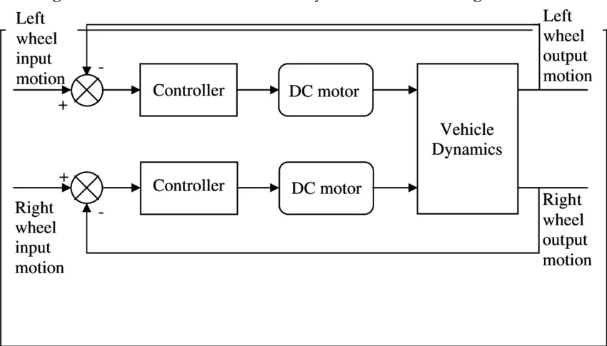
Every PCB design starts with a schematic—a blueprint of your circuit. Think of it as a map that shows how components like resistors, capacitors, microcontrollers (like an Arduino or Raspberry Pi), and motor drivers connect to each other. For robotics control, your schematic might include power lines for motors, signal lines for sensors, and ground connections to prevent noise.
As a beginner, start simple. Let’s say you’re designing a PCB for a small robot with two DC motors controlled by an Arduino Nano. Your schematic would include:
- An Arduino Nano as the brain of the robot.
- A motor driver IC (like the L298N) to handle motor power.
- Power input (e.g., a 9V battery connector).
- Connections for sensors (like ultrasonic sensors for obstacle detection).
The goal is to draw each connection accurately. A single wrong wire in the schematic can lead to a non-working PCB later. Use symbols for components (like a zigzag for resistors) and label everything clearly—trust me, it saves headaches down the road.
Step 2: Choosing the Right PCB Software for Beginners
Once your schematic is ready, you need software to turn it into a PCB layout. There are plenty of options out there, but for hobbyists, free or affordable tools are the best starting point. Here are three popular choices for PCB design tutorials and software:
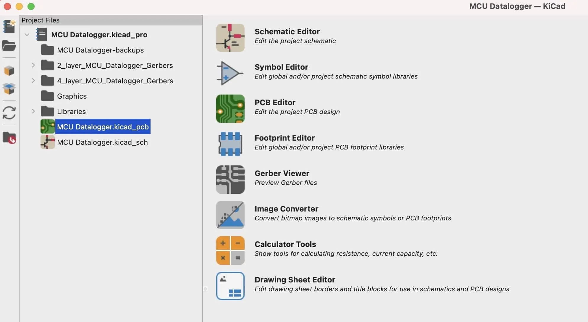
- KiCad: Free, open-source, and widely used by hobbyists. It’s great for beginners and has a supportive community. You can design schematics, create layouts, and export Gerber files for manufacturing.
- EAGLE: A bit more advanced but still beginner-friendly with a free version for small projects. It’s widely used in the industry and has tons of tutorials.
I started with KiCad because it’s free and has detailed guides online. For a robotics control PCB, you’ll use the PCB design software to place components on a virtual board and route traces (the copper paths that connect everything). Most software also checks for errors, like unconnected pins, which is a lifesaver for beginners.
Step 3: Creating a PCB Layout—Tips for Robotics Projects
Turning your schematic into a PCB layout is where the magic happens. The layout is the physical design of your board—where components sit and how traces connect them. For robotics control, you need to think about a few key things:
- Power and Ground Planes: Robots often draw a lot of current for motors (sometimes 1-2A or more at 12V). Use wide traces (at least 20-30 mils) for power lines to handle the load without overheating. A ground plane (a large copper area connected to ground) helps reduce noise, which is critical for sensor accuracy.
- Component Placement: Place your microcontroller near the center for easy access to all connections. Keep motor drivers close to the power input to minimize voltage drops. Group related components (like sensors) together to keep traces short.
- Signal Integrity: Avoid running signal traces (like those from sensors) near high-current motor lines to prevent interference. If you’re using a microcontroller with a clock speed of 16 MHz (like Arduino), keep traces short to avoid signal delays.
Start by placing big components first, like the microcontroller and motor driver, then add smaller ones like resistors and capacitors. Use the software’s auto-routing feature if you’re stuck, but manually check and adjust traces for better results. Remember, a good layout means less debugging later!
Step 4: Prototyping Your Robotics Control PCB
Before sending your design for manufacturing, prototyping is a must. Prototyping lets you test your PCB design on a small scale to catch errors. For hobbyists, there are two main ways to prototype:
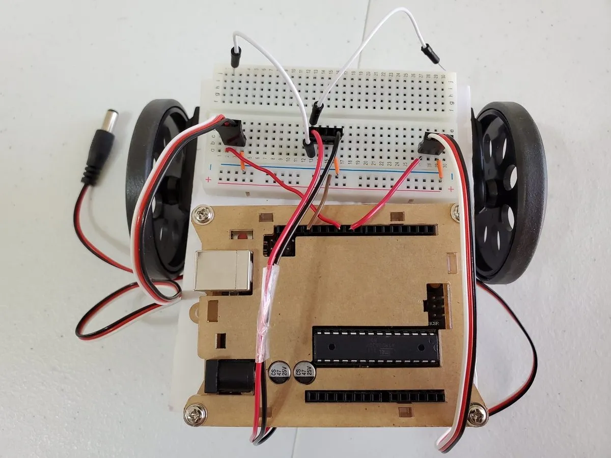
- Breadboard Testing: Build your circuit on a breadboard first using the same components from your schematic. Test if your robot’s motors spin correctly or if sensors send accurate data to the microcontroller. This step helps you confirm the schematic before committing to a PCB.
- DIY PCB Etching: If you’re adventurous, you can etch a simple PCB at home using a copper-clad board, ferric chloride, and a printed design. It’s messy and not ideal for complex designs, but it’s a cheap way to test a single board.
I’ve breadboarded every robotics project before designing a PCB. Once, I skipped this step and ended up with a board where the motor driver overheated due to thin traces. Lesson learned—prototype first! Expect to spend a few hours testing and tweaking during this stage.
Step 5: Generating Gerber Files for Manufacturing
Once your design is finalized and tested, it’s time to prepare for manufacturing. Gerber files are the industry-standard format that PCB manufacturers use to understand your design. These files include layers for copper traces, solder masks, silkscreen (text on the board), and drill holes.
In most PCB software like KiCad, exporting Gerber files is simple:
- Go to the “File” or “Export” menu in your software.
- Select “Gerber” as the format.
- Choose all necessary layers (top copper, bottom copper, solder mask, etc.).
- Generate a separate drill file for holes.
- Zip all files together to send to the manufacturer.
Double-check your Gerber files using a free online viewer. A common mistake is forgetting the drill file, which means your board won’t have holes for components. For a small robotics PCB (say, 5cm x 5cm), ALLPCB charge as little as $1 for a batch of 5 boards, so it’s affordable even for hobbyists.
Step 6: Manufacturing Your Robotics Control PCB
Now, it’s time to send your Gerber files to a manufacturer. For beginners, online services like ALLPCB is a great choice. They offer low-cost PCB prototyping (often under $10 for small orders) and fast shipping. Here’s how to get started:
- Upload your zipped Gerber files to the manufacturer’s website.
- Choose board specifications: thickness (usually 1.6mm), copper weight (1oz is standard), and color (green is cheapest).
- Select quantity—start with 5-10 boards in case of errors.
- Review the design preview to catch any issues.
Most manufacturers take 5-7 days to produce and ship boards. When they arrive, inspect them for defects like misaligned holes or broken traces. Then, solder your components (or use their assembly service if you’re not confident with soldering).
Common Mistakes to Avoid in Robotics PCB Design
As a beginner, you’ll likely make mistakes—and that’s okay! Here are a few pitfalls I’ve encountered and how to avoid them:
- Thin Traces for High Current: Motors can draw 1-2A or more. Use trace width calculators (available in most PCB software) to ensure traces are at least 20-30 mils wide for power lines.
- Ignoring Heat Dissipation: Motor drivers get hot. Leave space around them for airflow or add a heat sink if needed.
- Forgetting Bypass Capacitors: Add 0.1μF capacitors near microcontroller pins to filter noise. I skipped this once, and my robot kept resetting randomly.
Take your time to review each step. A small error in design can cost you time and money during manufacturing.
Final Thoughts: Bringing Your Robotics PCB to Life
Designing a robotics control PCB as a beginner is a rewarding journey. From sketching a schematic to holding a finished board in your hands, each step builds your skills as an electronic hobbyist. Start with a simple project, use free tools like KiCad, prototype on a breadboard, and don’t be afraid to make mistakes—they’re part of learning.
Remember, the key to a successful PCB is planning. Double-check your schematic, optimize your layout for robotics needs (like high-current traces and noise reduction), and test thoroughly before manufacturing. With affordable manufacturing options, there’s no reason not to try building your own board today.