ALLPCB


In the world of medical devices, pacemakers stand as life-saving innovations, regulating heartbeats for millions of patients worldwide. At the core of these devices lies the Printed Circuit Board (PCB), a critical component that must function flawlessly under demanding conditions. Ensuring the reliability and performance of pacemaker PCBs through rigorous testing and validation is non-negotiable. This comprehensive guide dives deep into the processes of PCB testing, pacemaker validation, and medical PCB reliability, offering actionable insights for engineers and manufacturers in the medical field. Whether you're seeking to understand PCB reliability or explore accelerated life testing, this blog covers it all.
At its essence, pacemaker PCB testing and validation involve a series of meticulous procedures to confirm that the PCB meets strict medical standards for safety, durability, and performance. From electrical testing to environmental stress assessments, every step ensures that the device can withstand real-world challenges over its lifespan. Let's explore these processes in detail, breaking down the key methods and best practices for achieving top-tier reliability in medical PCB design and manufacturing.
Why PCB Testing and Validation Matter for Pacemakers
Pacemakers are implantable medical devices that must operate without fail for years inside the human body. A single malfunction in the PCB could have life-threatening consequences. This is why PCB testing and validation are critical steps in the development process. These procedures not only verify the functionality of the board but also ensure compliance with stringent regulatory standards like ISO 13485 and FDA guidelines for medical devices.
Testing focuses on identifying potential weaknesses in the PCB design, such as signal integrity issues or material degradation, while validation confirms that the final product performs as intended in real-world scenarios. Together, these processes reduce the risk of failure, enhance patient safety, and build trust in the device’s reliability. For engineers, understanding the nuances of medical PCB testing is essential to delivering high-quality, dependable solutions.
The Unique Challenges of Medical PCB Testing
Unlike PCBs used in consumer electronics, those in pacemakers face unique challenges. They must operate in a bio-environment, resisting corrosion from bodily fluids while maintaining precise electrical performance. Additionally, they are subject to strict size constraints, often requiring miniaturized designs without compromising functionality. The testing process must account for these factors, simulating conditions like temperature fluctuations, mechanical stress, and long-term wear.
Key Methods for Pacemaker PCB Testing
Testing a PCB for a pacemaker involves a multi-layered approach, targeting different aspects of performance and durability. Below are the primary methods used to ensure that these critical components meet the required standards.
1. Electrical Performance Testing
Electrical testing is the foundation of PCB validation for pacemakers. It verifies that the board can handle the required voltage, current, and signal integrity necessary for proper operation. Common tests include:
- Continuity Testing: Ensures there are no open circuits or breaks in the PCB traces. This is critical for maintaining consistent electrical pathways in a pacemaker, where even a minor discontinuity could disrupt heart rhythm regulation.
- Insulation Resistance Testing: Measures the resistance between conductive paths to prevent short circuits. For pacemaker PCBs, insulation resistance must typically exceed 10 MΩ to avoid leakage currents that could harm the patient.
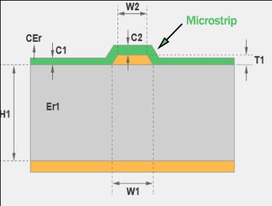
- Signal Integrity Analysis: Evaluates the quality of electrical signals transmitted across the PCB. Given that pacemakers rely on precise timing (often in the range of milliseconds), signal speeds and impedance values (e.g., 50 Ω for high-frequency lines) must be meticulously tested.
These tests are often conducted using automated test equipment (ATE) to ensure accuracy and repeatability, minimizing human error in the process.
2. Environmental Stress Testing
Pacemaker PCBs must endure harsh conditions, both during implantation and throughout their operational life. Environmental stress testing simulates these conditions to identify potential failures. Key tests include:
- Temperature Cycling: Exposes the PCB to extreme temperatures (e.g., -40°C to 85°C) to assess thermal expansion and contraction effects. This ensures the board can handle body temperature variations and external environmental factors during storage or transport.
- Humidity Testing: Evaluates the PCB’s resistance to moisture, which is critical since the device operates in a fluid-rich environment inside the body. Tests often simulate 85% relative humidity at 85°C for extended periods.
- Vibration and Shock Testing: Assesses the PCB’s ability to withstand mechanical stress, such as impacts during implantation or daily patient movement. Standards often require the PCB to endure vibrations at frequencies up to 500 Hz without failure.
3. Functional Testing for Pacemaker Validation
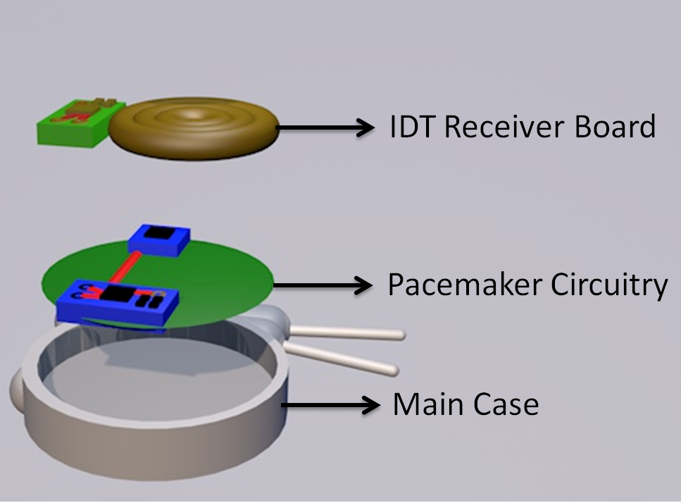
Functional testing goes beyond individual components, evaluating the PCB as part of the complete pacemaker system. This step ensures that the board integrates seamlessly with other device elements, delivering the intended therapeutic output. For instance, engineers might simulate heart signals to verify that the pacemaker responds correctly, adjusting pacing rates within 1-2 milliseconds as needed. This type of testing often involves custom test fixtures and software to mimic real-world conditions accurately.
Ensuring PCB Reliability Through Accelerated Life Testing
One of the most critical aspects of medical PCB testing is determining how the board will perform over its expected lifespan, which for pacemakers can be 10-15 years. Since real-time testing over such durations is impractical, accelerated life testing (ALT) is employed to simulate long-term use in a compressed timeframe.
What is Accelerated Life Testing (ALT)?
ALT subjects the PCB to intensified stress conditions—such as elevated temperatures, increased voltage, or rapid cycling—to accelerate aging processes. By applying these stressors, engineers can predict failure rates and identify weak points in the design. For example, a test might run at 125°C for 1000 hours to simulate 10 years of operation at body temperature (37°C). The data collected helps estimate the mean time to failure (MTTF), a key metric for reliability.
ALT is particularly valuable for pacemaker PCBs, where failure is not an option. It ensures that materials like solder joints and dielectric layers remain intact over time, even under constant electrical and thermal stress.
Benefits of ALT in Medical PCB Testing
- Early Detection of Failures: Identifies potential issues like delamination or trace cracking before the device reaches the market.
- Cost Efficiency: Reduces the need for long-term real-world testing, saving time and resources during development.
- Regulatory Compliance: Provides data to satisfy stringent medical standards, demonstrating that the PCB can endure its intended lifespan.
Regulatory Standards and Compliance in Medical PCB Testing
Compliance with international standards is a cornerstone of pacemaker PCB validation. Medical devices are subject to rigorous oversight to protect patient safety, and PCBs must meet specific benchmarks before approval. Key standards include:
- ISO 13485: Focuses on quality management systems for medical device manufacturing, ensuring consistent testing and documentation processes.
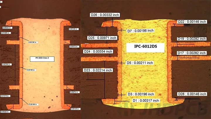
- IPC Class 3: Defines the highest reliability standards for PCBs used in life-supporting applications like pacemakers. This class mandates tighter tolerances (e.g., minimum trace widths of 0.1 mm) and stricter inspection criteria.
- FDA 21 CFR Part 820: Outlines quality system regulations for medical devices in the U.S., requiring thorough validation and traceability of all components, including PCBs.
Adhering to these standards during testing not only ensures safety but also streamlines the approval process, reducing time-to-market for new devices.
Best Practices for Pacemaker PCB Testing and Validation
To achieve optimal results in PCB testing for pacemakers, engineers and manufacturers should adopt the following best practices:
- Design for Testability (DFT): Incorporate test points and accessible pads during the design phase to simplify electrical and functional testing. This can reduce testing time by up to 30%.
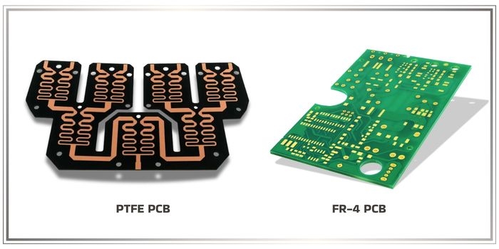
- Use High-Quality Materials: Select biocompatible and durable materials, such as FR-4 or polyimide substrates, to enhance long-term reliability in the body’s environment.
- Automate Where Possible: Leverage automated testing systems for consistency and precision, especially for repetitive tasks like continuity checks.
- Document Everything: Maintain detailed records of test conditions, results, and failures to support regulatory submissions and future improvements.
- Collaborate Across Teams: Ensure close communication between design, testing, and manufacturing teams to address issues early and optimize the PCB for reliability.
Common Challenges in Medical PCB Testing and How to Overcome Them
Testing pacemaker PCBs is not without its hurdles. Miniaturization, for instance, makes it difficult to access test points or apply probes without damaging delicate components. Additionally, simulating the exact conditions inside the human body remains a complex task, as factors like biofluid exposure are hard to replicate fully.
To address these challenges, consider using advanced tools like micro-probes for miniaturized boards and investing in sophisticated simulation software to model bio-environments more accurately. Partnering with experienced PCB manufacturing and testing providers can also help navigate these obstacles, ensuring that no detail is overlooked.
The Future of Pacemaker PCB Testing
As technology evolves, so do the methods for testing and validating pacemaker PCBs. Emerging trends include the use of artificial intelligence (AI) to predict failure modes during ALT, and the integration of IoT for real-time monitoring of test conditions. Additionally, advancements in biocompatible materials are paving the way for even more reliable and long-lasting PCBs, potentially extending pacemaker lifespans beyond the current 10-15 years.
Staying ahead of these trends is crucial for engineers and manufacturers aiming to deliver cutting-edge medical devices. By adopting innovative testing techniques and maintaining a commitment to quality, the industry can continue to improve patient outcomes through safer, more dependable technology.
Conclusion
Pacemaker PCB testing and validation are intricate yet indispensable processes in the development of life-saving medical devices. From electrical performance checks to accelerated life testing, each step plays a vital role in ensuring PCB reliability and patient safety. By adhering to strict regulatory standards, leveraging advanced testing methods, and following best practices, engineers can create PCBs that perform flawlessly under the most demanding conditions.
At ALLPCB, we understand the importance of precision and reliability in medical PCB manufacturing. Our expertise and state-of-the-art facilities are dedicated to supporting the creation of high-quality components for critical applications like pacemakers. Whether you're focused on PCB testing, pacemaker validation, or enhancing medical PCB reliability, this guide serves as a roadmap to achieving excellence in your projects.