 ALLPCB


In the fast-evolving world of unmanned aerial vehicles (UAVs), every gram and millimeter counts. If you're an engineer or designer working on drone technology, you might be searching for ways to achieve PCB miniaturization for drones, create a compact UAV PCB design, or implement high-density interconnect PCB for UAVs. You're in the right place! This blog post dives deep into proven miniaturization techniques for UAV PCB design, focusing on achieving a small form factor PCB for unmanned aerial vehicles and effective weight reduction in UAV PCB. We'll explore practical strategies, technical insights, and actionable tips to help you optimize your drone's performance.
At its core, PCB miniaturization for UAVs involves shrinking the size of circuit boards while maintaining or even enhancing functionality. This is crucial for drones where space is limited, and weight directly impacts flight efficiency. Below, we'll break down the essential techniques to achieve this, supported by detailed explanations and real-world applications.
Why Miniaturization Matters in UAV PCB Design
Miniaturization in UAV PCB design isn't just a trend; it's a necessity. Drones are used in diverse fields like agriculture, surveillance, and delivery services, where compact size and lightweight components are critical for longer flight times and better maneuverability. A smaller, lighter PCB reduces the overall weight of the drone, allowing for extended battery life and improved payload capacity.
For instance, reducing the PCB size by just 10% in a mid-sized drone can decrease the total weight by several grams, potentially increasing flight time by a few minutes. Additionally, a compact UAV PCB design enables tighter integration of components, which can enhance signal integrity by shortening trace lengths—often reducing signal delay by up to 20% in high-speed circuits.
Key Techniques for PCB Miniaturization in Drones
Let's dive into the core strategies for achieving PCB miniaturization for drones. These techniques are tailored to meet the unique demands of UAVs, balancing size, weight, and performance.
1. Leveraging High-Density Interconnect (HDI) Technology
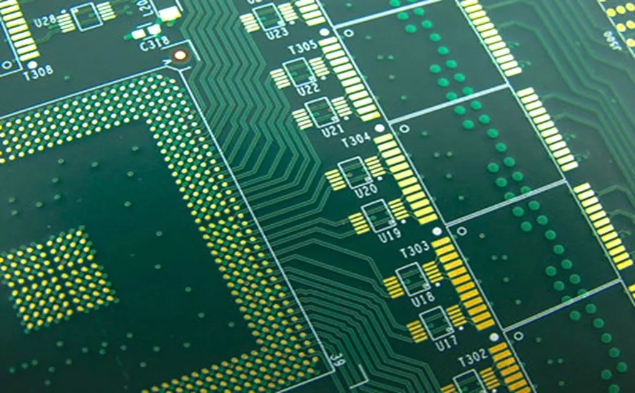
One of the most effective methods for creating a high-density interconnect PCB for UAVs is using HDI technology. HDI PCBs feature finer traces, smaller vias, and higher layer counts in a reduced footprint. This allows for more components to be packed into a smaller area without sacrificing functionality.
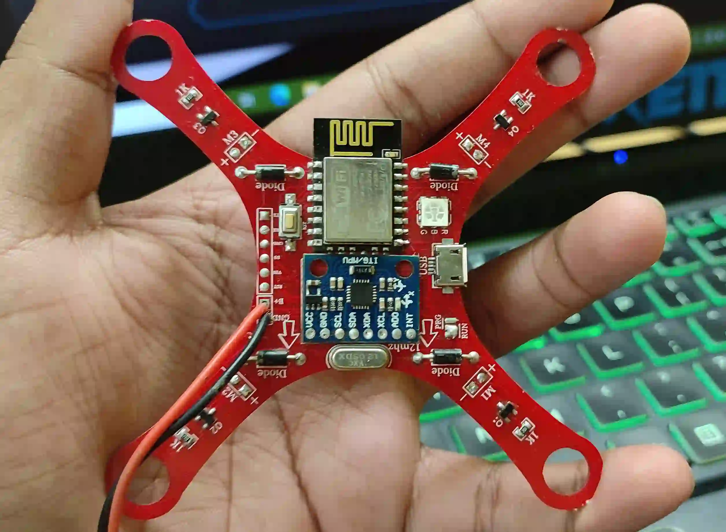
For example, HDI boards often use microvias with diameters as small as 0.1 mm, compared to traditional vias of 0.3 mm or larger. This reduction enables a 30-40% increase in component density. In a drone's flight controller, this means integrating processors, sensors, and communication modules into a board that might measure just 30 x 30 mm, significantly aiding weight reduction in UAV PCB.
HDI also improves signal integrity by minimizing trace lengths, which is vital for high-speed data transfer in drones equipped with real-time video streaming. By reducing impedance mismatches, HDI designs can maintain signal speeds above 1 GHz with minimal loss.
2. Optimizing Component Selection for Small Form Factor
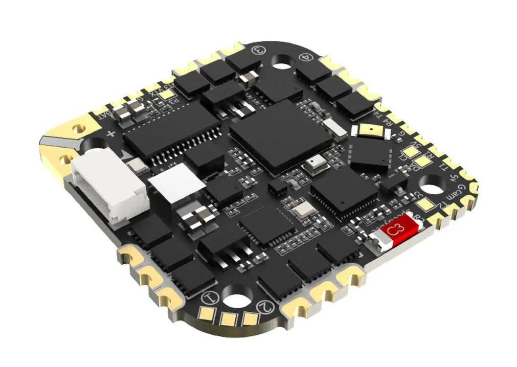
Choosing the right components is a cornerstone of designing a small form factor PCB for unmanned aerial vehicles. Surface-mount devices (SMDs) are preferred over through-hole components due to their smaller size and lighter weight. For instance, a typical SMD resistor might measure just 0.6 x 0.3 mm, compared to a through-hole resistor that could be ten times larger.
Additionally, using integrated circuits (ICs) with higher integration levels can combine multiple functions into a single chip. A modern drone flight controller might use a system-on-chip (SoC) that integrates a processor, memory, and input/output interfaces, reducing the need for separate components and cutting board space by up to 25%.
Pay attention to component weight as well. Lightweight materials in capacitors and inductors can contribute to weight reduction in UAV PCB. Even a reduction of 0.5 grams per component can add up across a board with dozens of parts.
3. Implementing Multi-Layer PCB Designs
Multi-layer PCBs are a game-changer for compact UAV PCB design. By stacking multiple layers of circuitry, you can drastically reduce the board's surface area while maintaining or increasing functionality. A typical drone PCB might use 4 to 8 layers, allowing power, ground, and signal traces to be separated for better electromagnetic interference (EMI) control.
For instance, a 6-layer PCB can reduce the board's footprint by 50% compared to a 2-layer design, fitting into tight spaces within a drone's frame. This also helps in routing high-speed signals with controlled impedance, often maintaining values around 50 ohms for optimal performance.
However, multi-layer designs must balance layer count with thickness. Each additional layer adds about 0.1-0.2 mm to the board's height, which could impact the drone's aerodynamics if not carefully managed.
4. Using Rigid-Flex PCBs for Space Efficiency
Rigid-flex PCBs combine the benefits of rigid and flexible circuits, offering a unique solution for small form factor PCB for unmanned aerial vehicles. These boards can bend and fold to fit into irregular spaces within a drone's body, reducing the need for connectors and cables that add weight and bulk.
In a typical UAV application, a rigid-flex PCB might connect the main flight controller to peripheral sensors, folding around other components to save space. This can reduce the overall PCB area by up to 30% and cut weight by eliminating additional wiring, supporting weight reduction in UAV PCB.
Rigid-flex designs also enhance reliability by reducing connection points, which are potential failure areas during high-vibration flight conditions. This is especially important for drones operating in harsh environments.
5. Advanced Routing and Placement Strategies
Efficient routing and component placement are critical for PCB miniaturization for drones. Automated design tools can optimize trace paths to minimize length and avoid congestion, reducing the board size. For instance, placing high-speed components closer to each other can shorten trace lengths, lowering signal delay and power consumption.
Additionally, consider a grid-based placement strategy to maximize space usage. Aligning components in a tight grid can reduce wasted space by 15-20%, allowing for a more compact UAV PCB design. Be mindful of thermal management, though—ensure heat-generating components like power regulators are spaced to avoid overheating, often maintaining a clearance of at least 2 mm.
Challenges in Miniaturizing UAV PCBs and How to Overcome Them
While miniaturization offers many benefits, it also comes with challenges. Addressing these hurdles is essential to ensure performance and reliability in UAV applications.
Thermal Management in Compact Designs
As components are packed closer together in a high-density interconnect PCB for UAVs, heat dissipation becomes a concern. Overheating can degrade performance or damage components, especially in drones where airflow might be limited.
To tackle this, incorporate thermal vias and heat sinks into the design. Thermal vias, often with a diameter of 0.3 mm, can transfer heat from hot components to a ground plane or external heat sink. Additionally, using materials with high thermal conductivity, such as copper layers with a thickness of 1-2 oz, can help manage temperatures effectively.
Signal Integrity and EMI Issues
Shrinking PCB size often means shorter distances between traces, increasing the risk of electromagnetic interference (EMI) and signal crosstalk. For drones relying on precise sensor data and communication, maintaining signal integrity is non-negotiable.
Use ground planes to shield sensitive signals and maintain trace impedance at around 50 ohms for high-speed lines. Separating analog and digital circuits on different layers in a multi-layer PCB can also reduce interference by up to 30%, ensuring reliable operation.
Manufacturing Constraints
Miniaturized PCBs often push the limits of manufacturing capabilities, especially with fine traces and microvias used in HDI designs. Ensure that your design adheres to standard manufacturing tolerances, such as minimum trace widths of 0.1 mm and via drill sizes of 0.15 mm, to avoid production issues.
Collaborating with a reliable PCB fabrication partner can help overcome these constraints by providing access to advanced manufacturing processes tailored for small form factor PCB for unmanned aerial vehicles.
Benefits of Miniaturization for UAV Performance
The effort put into PCB miniaturization for drones pays off with significant improvements in UAV performance. A smaller, lighter PCB directly contributes to better energy efficiency, often extending flight times by 10-15% due to reduced power draw and weight. This is a critical advantage for applications like aerial photography or long-range inspections.
Moreover, compact designs enable drones to carry additional payloads, such as advanced cameras or sensors, without exceeding weight limits. A compact UAV PCB design also improves the drone's center of gravity, enhancing stability during flight.
Future Trends in UAV PCB Miniaturization
The field of UAV PCB design is constantly evolving. Emerging technologies like 3D printing of PCBs and embedded components are set to revolutionize high-density interconnect PCB for UAVs. Embedding passive components like resistors and capacitors directly into the PCB substrate can reduce surface area by up to 40%, paving the way for even smaller designs.
Additionally, advancements in materials science are leading to lighter, more durable substrates that support weight reduction in UAV PCB. For example, using polyimide-based flexible materials can cut weight by 20% compared to traditional FR-4 boards while maintaining structural integrity.
Conclusion: Building the Future of UAVs with Miniaturized PCBs
Miniaturization is at the heart of modern UAV innovation. By adopting techniques like HDI technology, multi-layer designs, rigid-flex PCBs, and optimized component selection, you can achieve a small form factor PCB for unmanned aerial vehicles that enhances performance without compromising reliability. These strategies not only support weight reduction in UAV PCB but also enable drones to meet the demanding requirements of today's applications.
Whether you're designing a drone for commercial use or a specialized mission, focusing on PCB miniaturization for drones is a step toward building more efficient, capable, and versatile UAVs. With the right approach and tools, you can push the boundaries of what's possible in drone technology.


