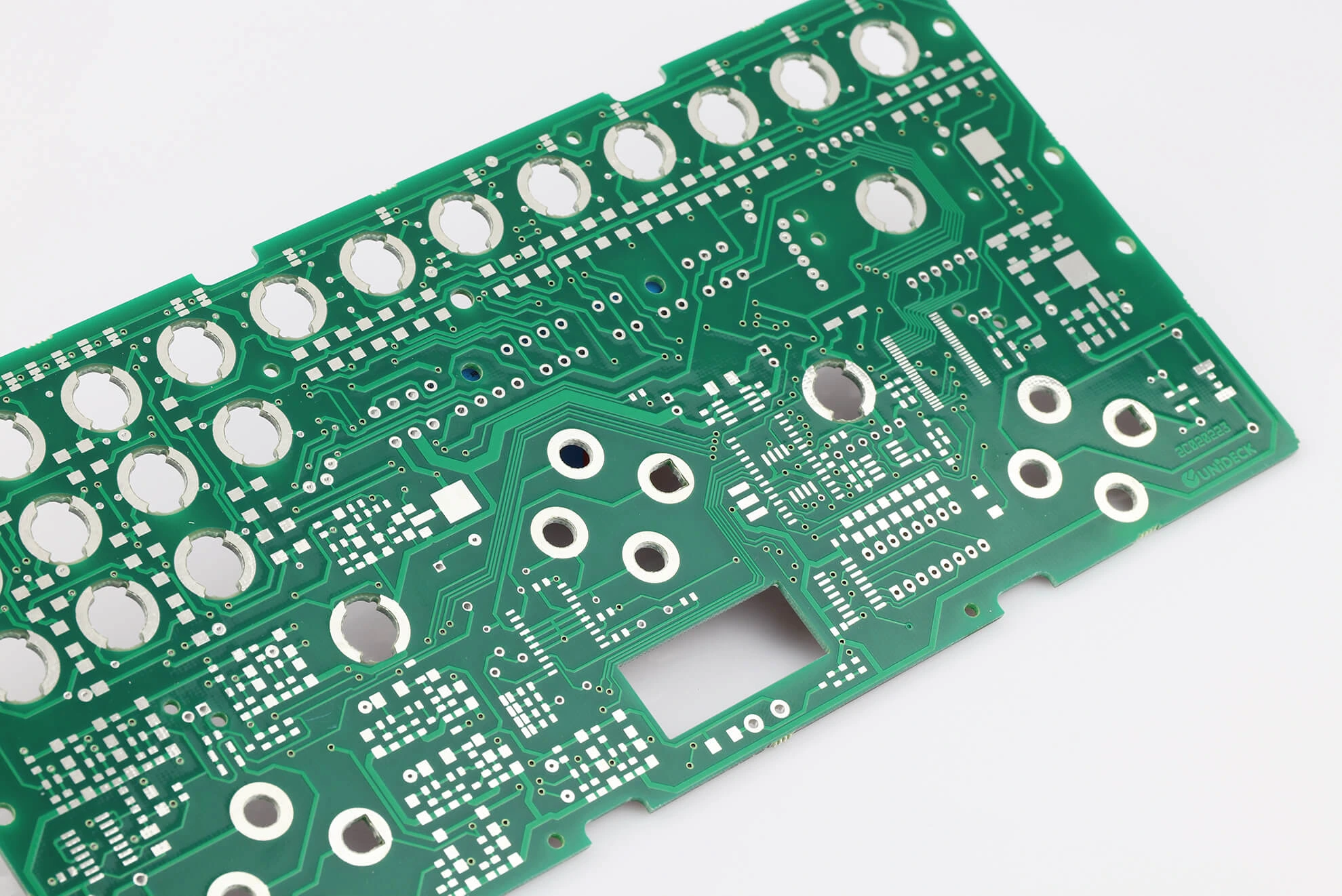
In the fast-evolving world of electric vehicles (EVs), battery management systems (BMS) play a critical role in ensuring safety, efficiency, and longevity of the battery pack. At the heart of a BMS lies high-precision current sensing, a process that monitors the flow of electricity to and from the battery. But how do engineers design PCBs for accurate current sensing under high-current conditions, and what challenges do they face? This blog post dives deep into high-precision current sensing in EV battery management PCBs, exploring design techniques like high current PCB design, precision shunt resistor selection, and kelvin sensing, as well as addressing challenges such as noise reduction techniques, current sensor calibration, and EMC compliance.
Whether you're an engineer working on EV designs or a professional seeking to understand the intricacies of BMS PCB design, this guide offers actionable insights and practical solutions to achieve reliable and accurate current measurements.
Why High-Precision Current Sensing Matters in EV Battery Management
Current sensing in EV battery management systems is essential for several reasons. It helps monitor the state of charge (SoC), detect overcurrent conditions, and ensure the battery operates within safe limits. Accurate current measurements directly impact the vehicle's range estimation, thermal management, and overall safety. Without precise sensing, an EV's BMS could fail to detect faults, leading to potential battery damage or even hazardous situations like thermal runaway.
In high-current environments, where currents can reach hundreds of amperes (e.g., 200A to 500A in typical EV battery packs), even small inaccuracies in measurement can lead to significant errors. For instance, a 1% error in a 300A current reading translates to a 3A discrepancy, which can skew SoC calculations over time. This makes high-precision current sensing not just a design goal but a necessity.
Key Design Techniques for High-Precision Current Sensing in PCBs
Designing PCBs for high-precision current sensing in EV battery management systems requires careful attention to layout, component selection, and measurement techniques. Below, we explore the most effective design strategies to achieve accurate results.
1. High Current PCB Design: Handling Power with Precision
In EV applications, PCBs must handle high currents without overheating or introducing errors in current sensing. High current PCB design focuses on minimizing resistance and ensuring thermal stability. Here are some key considerations:
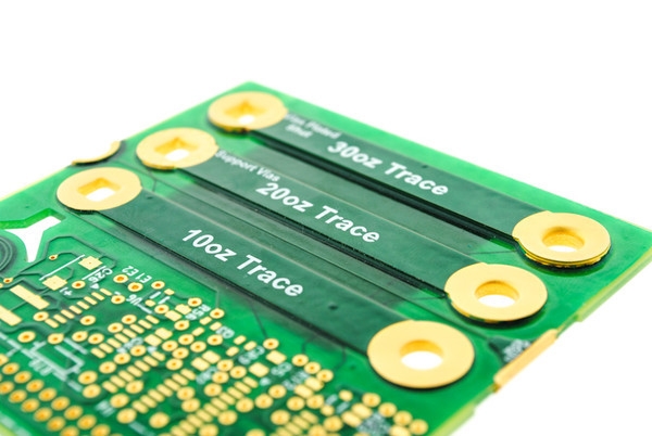
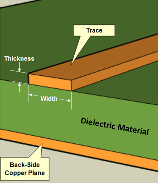
- Trace Width and Thickness: Use wider and thicker copper traces to reduce resistance and heat generation. For example, a trace carrying 100A may require a width of 10mm or more with a copper thickness of 2oz or higher, depending on the PCB stack-up.
- Thermal Management: Incorporate thermal vias and heat sinks to dissipate heat from high-current paths. Overheating can alter component behavior and affect measurement accuracy.
- Short Current Paths: Design the PCB layout to minimize the length of high-current paths, reducing voltage drops and parasitic inductance. A voltage drop of just 1mV across a trace can introduce errors in sensing applications.
2. Precision Shunt Resistor Selection: The Foundation of Accurate Sensing
A shunt resistor is often the go-to component for current sensing in EV BMS due to its simplicity and cost-effectiveness. However, precision shunt resistor selection is critical to achieving accurate measurements. Here's what to consider:
- Low Resistance Values: Shunt resistors typically have very low resistance (e.g., 100μΩ to 1mΩ) to minimize power loss. For a 300A current, a 100μΩ shunt produces a 30mV drop, which is measurable yet energy-efficient.
- Temperature Coefficient: Choose resistors with a low temperature coefficient of resistance (TCR), such as 50ppm/°C or lower, to ensure stable performance across temperature variations in an EV (e.g., -40°C to 85°C).
- Power Rating: Ensure the shunt can handle the power dissipation. For a 300A current through a 100μΩ shunt, power dissipation is I2R = 9W, so select a resistor with a sufficient power rating and heat dissipation capability.
3. Kelvin Sensing: Eliminating Measurement Errors
One of the most effective techniques for accurate current measurement is kelvin sensing, also known as four-wire sensing. This method separates the current-carrying path from the voltage measurement path, eliminating errors caused by trace resistance and contact points.
- How It Works: In kelvin sensing, two connections are made to the shunt resistor for current flow, and two separate connections are used to measure the voltage drop. This ensures that the measured voltage is unaffected by the resistance of the current-carrying traces.
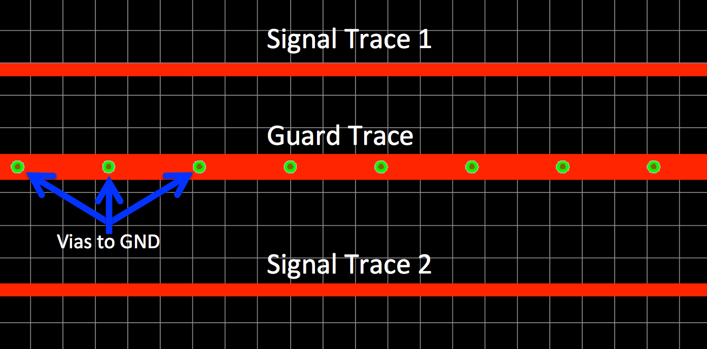
- Implementation: Place the sense traces as close as possible to the shunt resistor pads to avoid interference. Ensure that the sense lines are routed away from high-current paths to prevent noise pickup.
Without kelvin sensing, a typical PCB trace resistance of 0.5mΩ could add a 150mV error to a 300A measurement, significantly skewing results. With kelvin sensing, this error is virtually eliminated.
4. Current Sensor Calibration: Ensuring Long-Term Accuracy
Even with the best design, current sensors can drift over time due to temperature changes, aging, or manufacturing tolerances. Current sensor calibration is essential to maintain accuracy throughout the EV's lifespan.
- Initial Calibration: Perform calibration during manufacturing using a known current source (e.g., 100A) to establish baseline readings. Store calibration data in the BMS firmware for reference.
- Periodic Calibration: Implement algorithms in the BMS to detect and correct drift during operation. For instance, use zero-current conditions (when the vehicle is off) to recalibrate offset errors.
- Temperature Compensation: Account for temperature effects by integrating temperature sensors near the shunt and applying correction factors based on the resistor's TCR.
Proper calibration can reduce measurement errors from ±2% to below ±0.1%, ensuring reliable SoC estimation and fault detection.
Challenges in High-Precision Current Sensing for EV BMS PCBs
While the techniques above help achieve accurate current sensing, several challenges can complicate the design process. Addressing these hurdles is crucial for a robust and reliable BMS.
1. Noise Reduction Techniques: Filtering Out Interference
EV environments are electrically noisy due to high-power inverters, motors, and switching regulators. This noise can interfere with current sensing, leading to inaccurate readings. Noise reduction techniques are vital for maintaining precision.
- Shielding: Use ground planes and shielding around sensitive analog circuitry to block electromagnetic interference (EMI). For example, place a ground plane beneath the current sensing circuit to reduce noise coupling.
- Filtering: Incorporate low-pass filters (e.g., with a cutoff frequency of 1kHz) in the signal path to remove high-frequency noise while preserving the current signal.
- Differential Amplifiers: Use differential amplifiers to measure the voltage drop across the shunt resistor. These amplifiers reject common-mode noise, improving signal integrity.
Without proper noise reduction, a noise-induced error of 1mV in a 30mV signal (from a 100μΩ shunt at 300A) could result in a 3.3% measurement error, which is unacceptable for BMS applications.
2. EMC Compliance: Meeting Stringent Standards
Electromagnetic compatibility (EMC compliance) is a significant challenge in EV PCB design. EVs must adhere to strict EMC standards to prevent interference with other electronic systems and ensure safety.
- Conducted Emissions: High-current switching in EV systems can generate conducted noise through power lines. Use EMI filters and proper grounding to minimize these emissions.
- Radiated Emissions: High-current traces and loops act as antennas, radiating EMI. Minimize loop areas in the PCB layout and use shielding to reduce radiated noise.
- Testing: Perform pre-compliance EMC testing during the design phase to identify and address issues early. Standards like CISPR 25 for automotive electronics set limits on emissions that must be met.
Failure to achieve EMC compliance can result in costly redesigns or delays in product certification, making it a critical focus area for engineers.
3. Balancing Cost and Performance
High-precision components like low-TCR shunt resistors and high-accuracy amplifiers often come with a higher price tag. Additionally, advanced techniques like kelvin sensing require more complex PCB layouts, increasing manufacturing costs. Engineers must strike a balance between achieving the required accuracy and keeping costs manageable for mass production.
For example, while a high-end shunt resistor with a TCR of 10ppm/°C offers excellent stability, a more affordable option with 50ppm/°C may suffice with proper temperature compensation in the BMS software.
Practical Tips for Implementing High-Precision Current Sensing
To wrap up, here are some practical tips to help engineers design effective current sensing solutions for EV battery management PCBs:
- Start with simulation tools to model high-current paths and thermal behavior before finalizing the PCB layout. This can help identify potential issues early.
- Collaborate with component suppliers to select shunt resistors and amplifiers that match the specific requirements of your EV application.
- Iterate on prototypes, testing for noise, thermal performance, and EMC under real-world conditions (e.g., temperature cycling from -40°C to 85°C).
- Document calibration procedures and ensure they are integrated into the BMS firmware for consistent performance over time.
Conclusion: Mastering Current Sensing for EV Battery Management
High-precision current sensing is a cornerstone of effective battery management systems in electric vehicles. By leveraging techniques like high current PCB design, precision shunt resistor selection, and kelvin sensing, engineers can achieve accurate measurements even in challenging high-current environments. However, overcoming obstacles such as noise, EMC compliance, and cost constraints requires a combination of careful design, robust noise reduction techniques, and thorough current sensor calibration.
At ALLPCB, we understand the complexities of designing PCBs for EV applications. Our expertise in high-quality PCB manufacturing and assembly ensures that your designs meet the stringent demands of battery management systems. Whether you're tackling EMC compliance or optimizing for high currents, we're here to support your journey toward innovative and reliable EV solutions.
By focusing on these design techniques and addressing the associated challenges, you can build BMS PCBs that deliver the precision and reliability needed to power the future of electric mobility.
 ALLPCB


